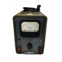
TM 11-6625-1514-15
Section V
TROUBLE
PROBABLE CAUSE
REMEDY
1. Power indicator lamp does not light.
a. Fuse F1 burned out.
a. Replace fuse F1. If replaced fuse blows,
check items 2 and 3 below.
b. Power indicator lamp DS1 defective.
b. Replace power indicator lamp DS1.
c. Defective a-c power cable.
c. Repair or replace power cable.
d. Power switch S2 defective.
d. Replace Power switch S2.
e. Transformer T1 primary winding
e. Check connections of transformer T1 primary
terminals incorrectly connected. winding; rewire if necessary.
2. Fuse F1 blows immediately when Power switch S2 is operated to ON.
a. Tube V6 shorted. a. Replace rectifier tube V6.
b. Rectifier CR3 defective. b. Replace heater rectifier CR3.
c. Short circuit in transformer T1 or in
c. Remove all tubes, and check transformer
circuit wiring. windings. Replace transformer T1 if
defective. Check for short circuit.
3. Fuse F1 blows after Power switch S2 has been operated to ON and tube heaters have warmed up.
Short in power supply circuit. Check for short circuit at cathodes V6 and V7.
Replace defective component.
4. Power indicator lamp lights; voltmeter does not indicate on all ranges.
a. Power supply or voltage regulator a. Check tubes V6, V9, V7, and V8 in turn.
circuits defective. Check high-voltage winding of transformer
T1. Replace defective component.
b. Rectifier CR3 or circuit component
b. Check for 12.6 volts dc across output of
defective.
rectifier CR3, Check resistors R66 and R68.
If tubes V1 and V2 are not lighted, check
capacitor C39. Replace defective component.
c. Diode CR1 or CR2 defective.
c. Replace diode (paragraph 5-15).
5. Meter indication normal on low ranges (.001 to .3 volts). Meter sensitivity distorted on
high-voltage ranges (1 to 300 volts).
Compensated 1000:1 divider defective.
Check C4 and R4. Replace defective component.
6. Meter indicates low on all ranges.
a. Check B+ voltage (paragraph 5-20). Check
a. Low amplifier gain.
tubes V2 through V5 for low emission. If
any tube is replaced, check and recalibrate
the voltmeter (paragraph 5-22).
b. Diode CR1 or CR2 defective.
b. Replace diode (paragraph 5-15).
7. Meter indication unstable or erratic.
a. Power supply, circuit defective.
a. Check heaters and B+ voltage. Replace
defective component.
b. Amplifier tube V1, V2, V3, V4, and
b. Check V1 through V5 for microphonics or
V5 defective.
noise. If tube is replaced, check and
recalibrate the voltmeter (paragraph 5-22).
8. Meter indication normal on .001 and 1 volt range.
Meter sensitivity distorted on all other
ranges (.003, .01, .03, .1, .3, 3, 10, 30, 100, and 300 volts).
Faulty RANGE switch S1.
Check switch contacts of S1. Replace RANGE
switch S1 if defective (paragraph 5-16).
Figure 5-5. Trouble-Shooting Procedure
5-6
00102-2

 Loading...