rj
0 0
10
ra,
0 0 0
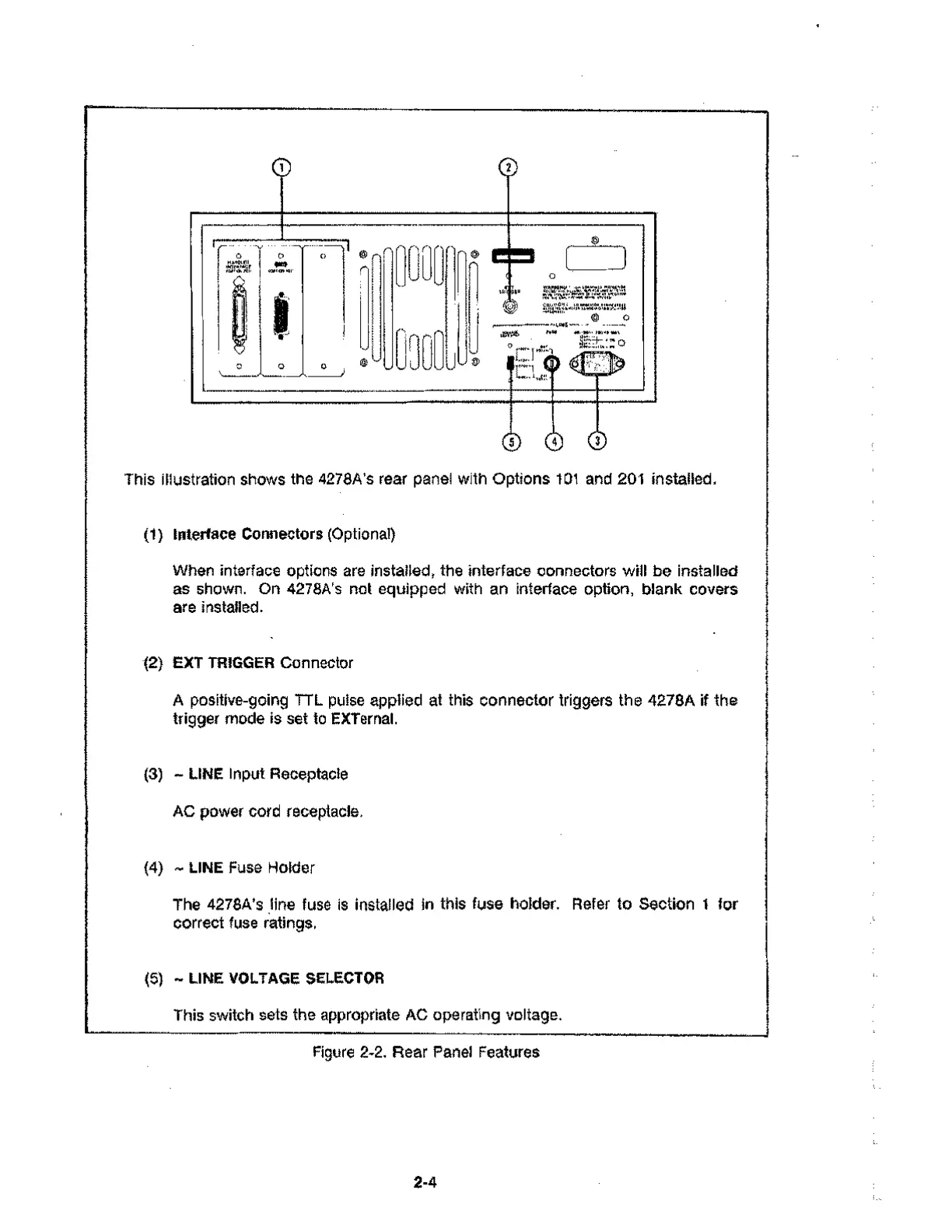
This illustration shows the 4278A's rear panel with Options 101 and 201 installed.
(1) Interface Connectors (Optional)
When interface options are installed, the interface connectors will be installed
as shown. On 4278A's not equipped with an interface option, blank covers
are installed.
(2) EXT TRIGGER Connector
A positive-going TTL pulse applied at this connector triggers the 4278A if the
trigger mode is set to EXTernal.
(3) - LINE Input Receptacle
AC power cord receptacle.
(4) - LINE Fuse Holder
The 4278A's line fuse is installed in this fuse holder. Refer to Section 1 for
correct fuse ratings.
(5) - LINE VOLTAGE SELECTOR
This switch sets the appropriate AC operating voltage.
Figure 2-2. Rear Panel Features
2-4