Procedure:
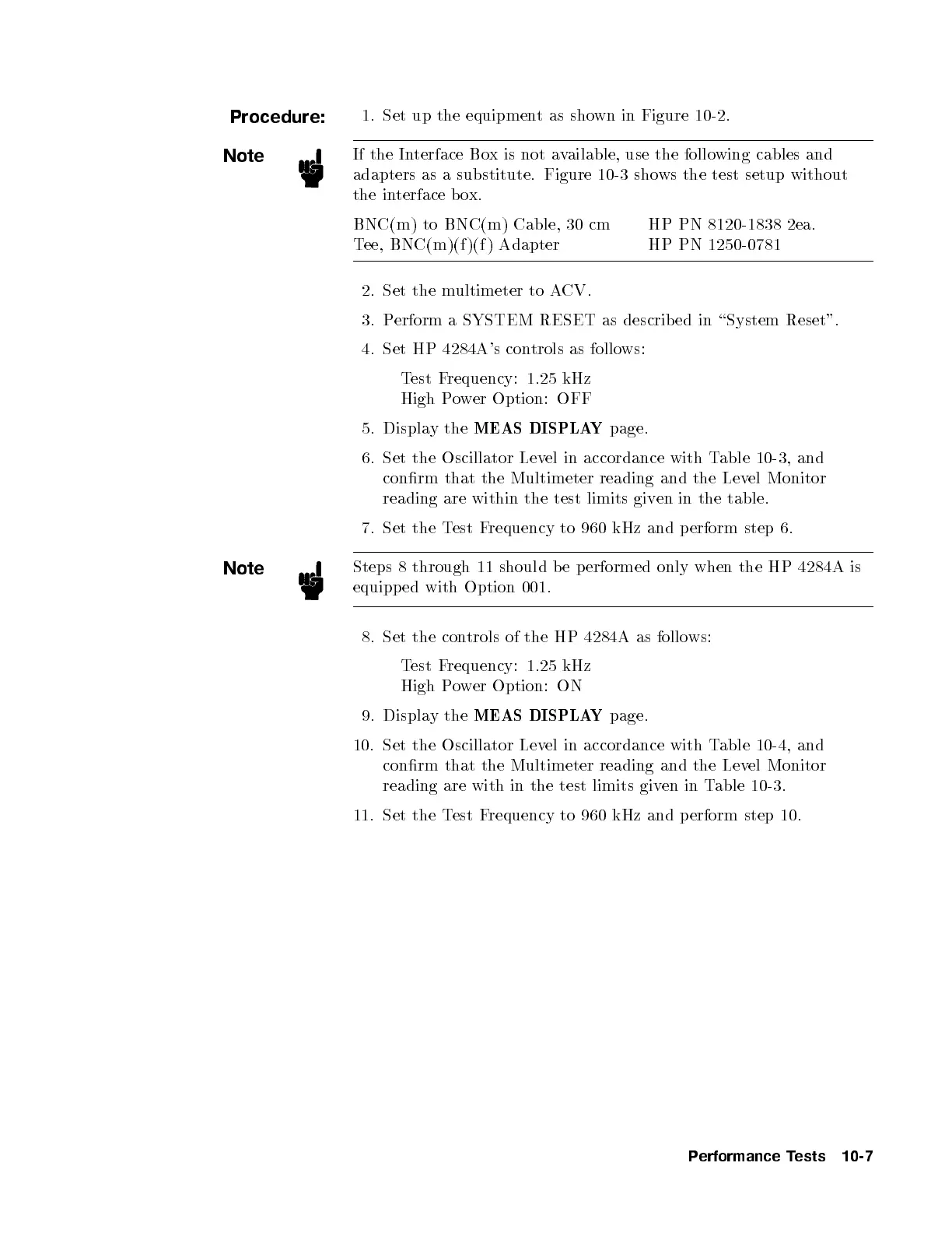
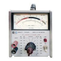
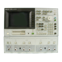
1. Set up the equipment as shown in Figure 10-2.
Note
If the Interface Box is not available, use the following cables and
adapters as a substitute. Figure 10-3 shows the test setup without
the interface box.
BNC(m) to BNC(m) Cable, 30 cm HP PN 8120-1838 2ea.
Tee, BNC(m)(f )(f ) Adapter HP PN 1250-0781
2. Set the multimeter to ACV.
3. Perform a SYSTEM RESET as describ ed in \System Reset".
4. Set HP 4284A's controls as follows:
Test Frequency: 1.25 kHz
High Power Option: OFF
5. Display the
MEAS DISPLAY
page.
6. Set the Oscillator Level in accordance with Table 10-3, and
conrm that the Multimeter reading and the Level Monitor
reading are within the test limits given in the table.
7. Set the Test Frequency to 960 kHz and perform step 6.
Note
Steps 8 through 11 should be performed only when the HP 4284A is
equipped with Option 001.
8. Set the controls of the HP 4284A as follows:
Test Frequency: 1.25 kHz
High Power Option: ON
9. Display the
MEAS DISPLAY
page.
10. Set the Oscillator Level in accordance with Table 10-4, and
conrm that the Multimeter reading and the Level Monitor
reading are with in the test limits given in Table 10-3.
11. Set the Test Frequency to 960 kHz and perform step 10.
Performance Tests 10-7


 To Next Page