Note
DC p ower for the bias interface simulator can be supplied from the
HP 4284A instead of from an external DC p ower supply.For further
details, see \Supplying DC Power to the Simulator".
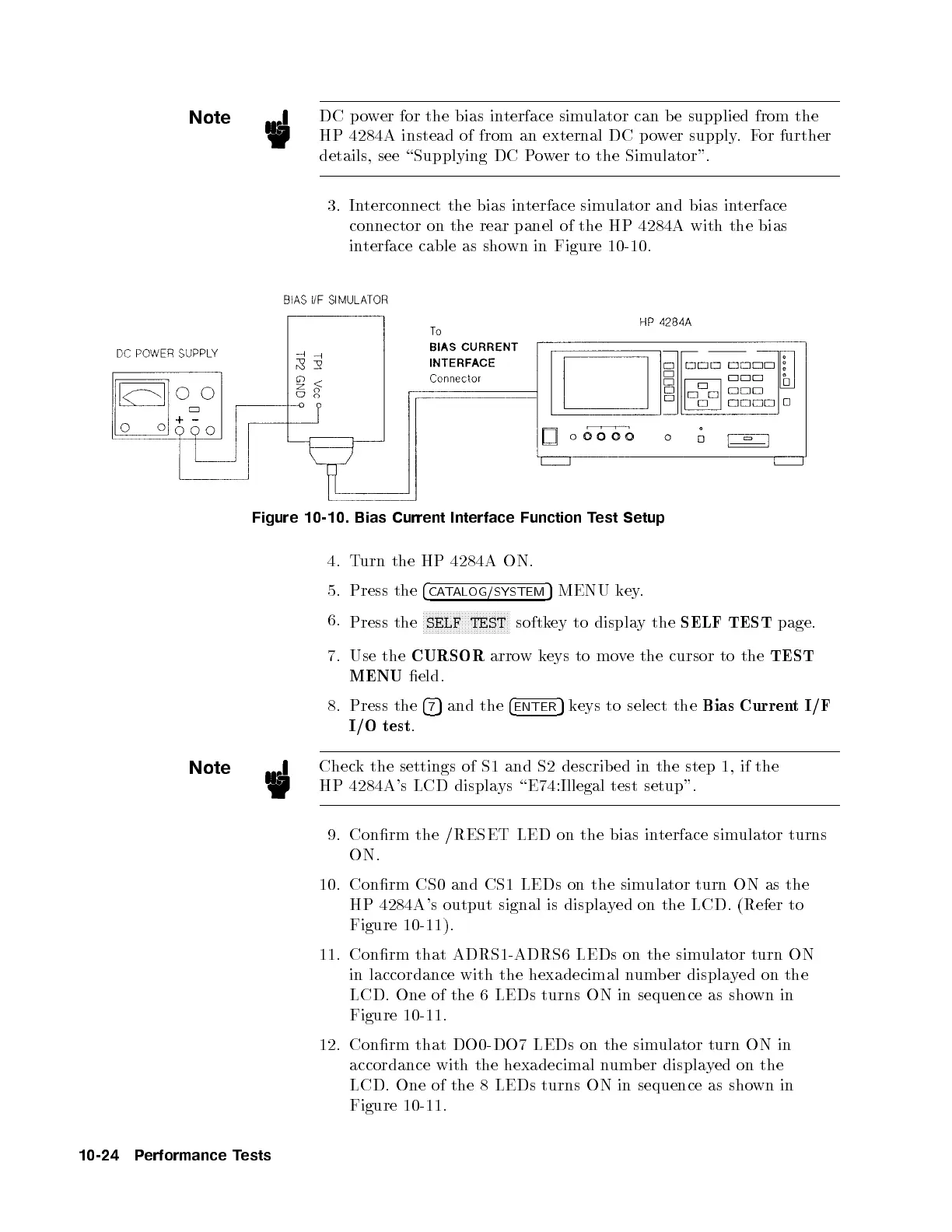
3. Interconnect the bias interface simulator and bias interface
connector on the rear panel of the HP 4284A with the bias
interface cable as shown in Figure 10-10.
Figure 10-10. Bias Current Interface Function Test Setup
4. Turn the HP 4284A ON.
5. Press the
4
CATALOG/SYSTEM
5
MENU key.
6.
Press the
NNNNNNNNNNNNNNNNNNNNNNNNNNNNN
SELF TEST
softkey to display the
SELF TEST
page.
7. Use the
CURSOR
arrow keys to move the cursor to the
TEST
MENU
eld.
8. Press the
4
7
5
and the
4
ENTER
5
keys to select the
Bias Current I/F
I/O test
.
Note
Check the settings of S1 and S2 described in the step 1, if the
HP 4284A's LCD displays \E74:Illegal test setup".
9. Conrm the /RESET LED on the bias interface simulator turns
ON.
10. Conrm CS0 and CS1 LEDs on the sim
ulator turn ON as the
HP 4284A's output signal is displayed on the LCD. (Refer to
Figure 10-11).
11. Conrm that ADRS1-ADRS6 LEDs on the simulator turn ON
in laccordance with the hexadecimal number displayed on the
LCD. One of the 6 LEDs turns ON in sequence as shown in
Figure 10-11.
12. Conrm that DO0-DO7 LEDs on the sim
ulator turn ON in
accordance with the hexadecimal number displayed on the
LCD. One of the 8 LEDs turns ON in sequence as sho
wn in
Figure 10-11.
10-24 Performance Tests


 To Next Page