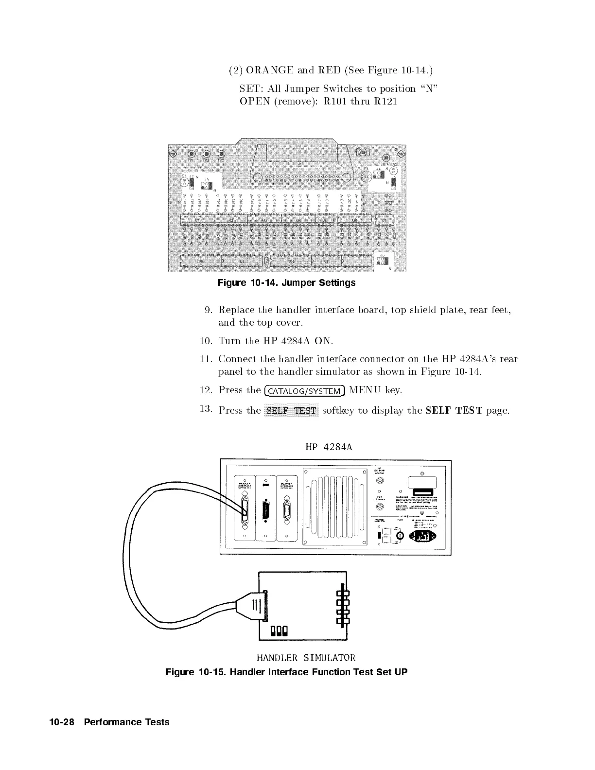
(2) ORANGE and RED (See Figure 10-14.)
SET: All Jump er Switches to p osition \N"
OPEN (remove): R101 thru R121
Figure 10-14. Jumper Settings
9. Replace the handler interface b oard, top shield plate, rear feet,
and the top cover.
10. Turn the HP 4284A ON.
11. Connect the handler interface connector on the HP 4284A's rear
panel to the handler simulator as shown in Figure 10-14.
12. Press the
4
CATALOG/SYSTEM
5
MENU key.
13.
Press the
NNNNNNNNNNNNNNNNNNNNNNNNNNNNN
SELF TEST
softkey to display the
SELF TEST
page.
Figure 10-15. Handler Interface Function Test Set UP
10-28 Performance Tests


 To Next Page