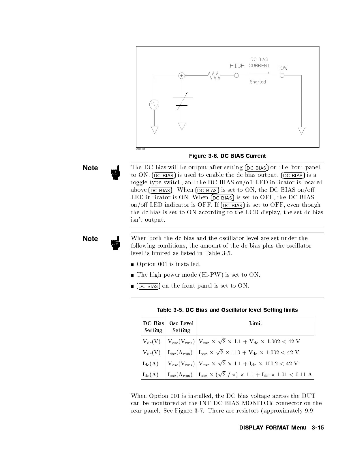
Figure 3-6. DC BIAS Current
Note
The DC bias will b e output after setting
4
DC BIAS
5
on the front panel
to ON.
4
DC BIAS
5
is used to enable the dc bias output.
4
DC BIAS
5
is a
toggle type switch, and the DC BIAS on/o LED indicator is lo cated
above
4
DC BIAS
5
. When
4
DC BIAS
5
is set to ON, the DC BIAS on/o
LED indicator is ON. When
4
DC BIAS
5
is set to OFF, the DC BIAS
on/o LED indicator is OFF. If
4
DC BIAS
5
is set to OFF, even though
the dc bias is set to ON according to the LCD displa
y, the set dc bias
isn't output.
Note
When b oth the dc bias and the oscillator lev
el are set under the
following conditions, the amount of the dc bias plus the oscillator
level is limited as listed in Table 3-5.
Option 001 is installed.
The high p ower mo de (Hi-PW) is set to ON.
4
DC BIAS
5
on the front panel is set to ON.
Table 3-5. DC Bias and Oscillator level Setting limits
DC Bias
Setting
Osc Level
Setting
Limit
V
dc
(V) V
osc
(V
rms
)V
osc
2
p
2
2
1.1 + V
dc
2
1.002
<
42 V
V
dc
(V) I
osc
(A
rms
) I
osc
2
p
2
2
110 + V
dc
2
1.002
<
42 V
I
dc
(A) V
osc
(V
rms
)V
osc
2
p
2
2
1.1 + I
dc
2
100.2
<
42 V
I
dc
(A) I
osc
(A
rms
) I
osc
2
(
p
2/
)
2
1.1 + I
dc
2
1.01
<
0.11 A
When Option 001 is installed, the DC bias v
oltage across the DUT
can b e monitored at the INT DC BIAS MONITOR connector on the
rear panel. See Figure 3-7. There are resistors (appro
ximately 9.9
DISPLAYFORMAT Menu 3-15