•
•
Model 436A
Installation
SECTION
II
INSTALLATION
2-1. INTRODUCTION
2-2. This section provides all information neces-
sary
to
install
the
Power Meter. Covered in
the
section are initial inspection, power requirements,
line voltage selection, interconnection, circuit
options, mounting, storage,
and
repackaging for
shipment.
2-3.
INITIAL
INSPECTION
2-4. Inspect the shipping container for damage.
If
the
shipping container
or
cushioning material
is
damaged,
it
should be
kept
until
the
contents
of
the
shipment have been checked for completeness
and
the
instrument has been checked mechanically
and
electrically. The contents of
the
shipment
should be
as
shown in Figure 1-1. Procedures for
checking electrical performance are given in
Section IV.
If
the
contents
are incomplete,
if
there
is mechanical damage
or
defect,
or
if
the
instru-
ment
does
not
pass
the
electrical performance test,
notify
the
nearest Hewlett-Packard office.
If
the
shipping container is. damaged,
or
the
cushioning
material shows signs
of
stress, notify
the
carrier
as
well
as
the
Hewlett-Packard office. Keep
the
shipping materials
for
the
carrier's inspection.
2-5. PREPARATION FOR
USE
2-6. Power Requirements
2-7.
The
Power Meter requires a power source
of
100,
120,
220,
or
240 Vac,
+5%,
-10%,
48
to
440
Hz single phase. Power consumption
is
approx-
imately
20
watts.
I WARNING I
If
this instrument is
to
be energized
via
an
autotransformer for voltage reduction,
make
sure
the
common
terminal
is
connected
to
the
earthed pole
of
the
power
source.
2-8. Line Voltage and Fuse Selection
BEFORE
PLUGGING THIS
INSTRUMENT
into
the
Mains (line) voltage,
be
sure the cor-
rect voltage and fuse have been selected.
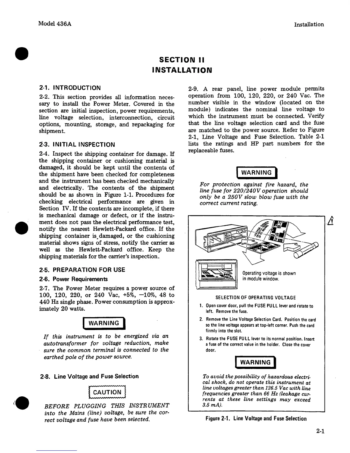
2-9. A rear panel, line power module permits
operation from
100,
120,
220,
or
240
Vac. The
number
visible in
the
window (located on
the
module) indicates
the
nominal line voltage
to
which
the
instrument
must
be connected. Verify
that
the
line voltage selection card
and
the
fuse
are
matched
to
the
power source. Refer
to
Figure
2-1, Line Voltage
and
Fuse Selection. Table 2-1
lists
the
ratings and HP
part
numbers for the
replaceable fuses.
I WARNING I
For protection against fire hazard, the
line fuse for
220/240Voperation
should
only
be a
250V
slow blow fuse
with
the
correct current rating.
Operating
voltage
is
shown
in
module
window.
SELECTION
OF
OPERATING
VOLTAGE
1.
Open
cover
door,
pull
the
FUSE
PULL
lever
and
rotate
to
left.
Remove
the
fuse.
2.
Remove
the
Line
Voltage
Selection
Card.
Position
the
card
so
the
line
voltage
appears
at
top-left
corner.
Push
the
card
firmly
into
the
slot.
3.
Rotate
the
FUSE
PU
LL
lever
to
its
normal
position.
Insert
a
fuse
of
the
correct
value
in
the
holder.
Close
the
cover
door.
I WARNING I
To
avoid
the
possibility
of
hazardous electri-
cal shock,
do
not
operate
this
instrument
at
line voltages greater
than
126.5 Vac
with
line
frequencies greater
than
66
Hz
(leakage
cur-
rents
at
these
line
settings
may
exceed
3.5 mA).
Figure
2-1.
Line
Voltage
and
Fuse
Selection
2-1
 Loading...


