•
•
•
Model
436A
Operation
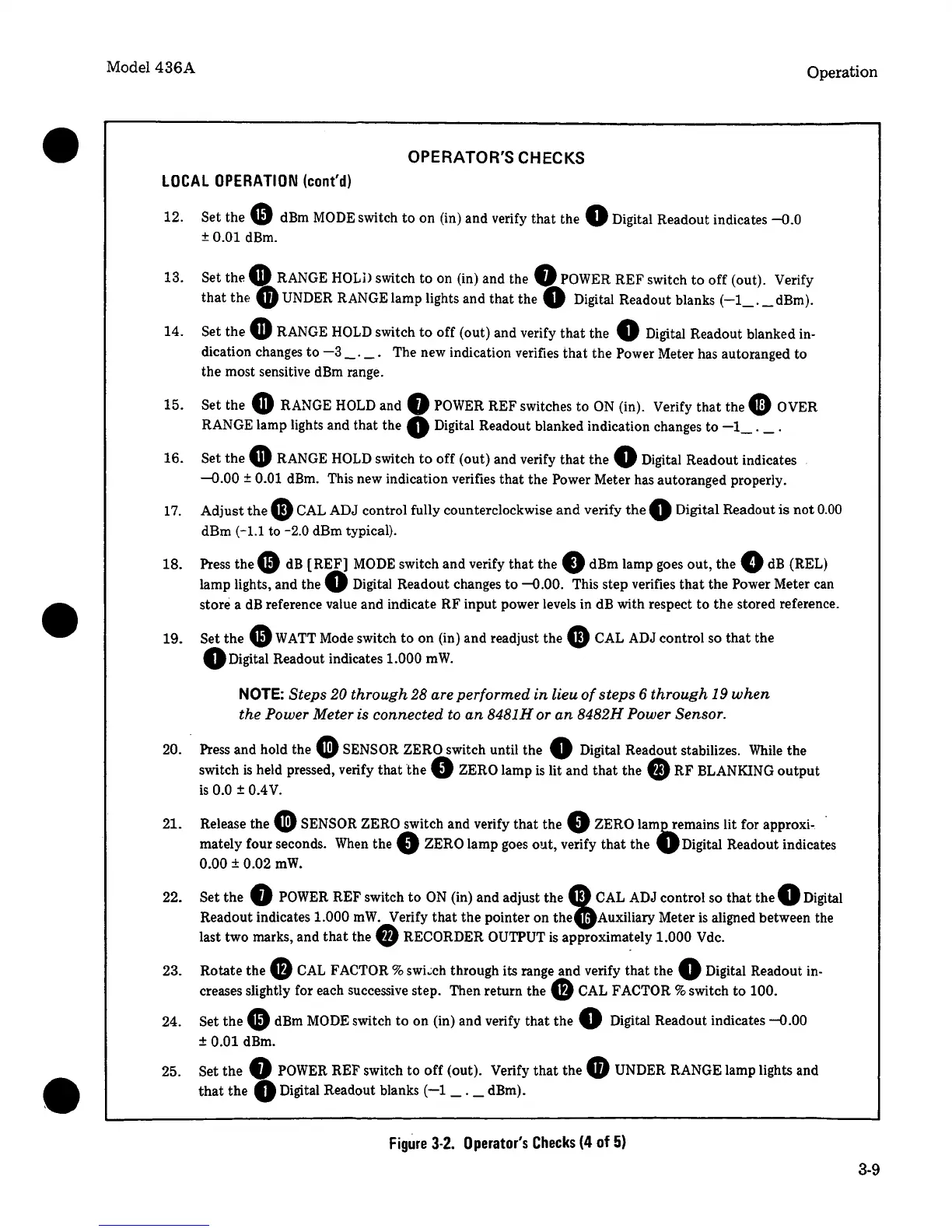
OPERATOR'S CHECKS
LOCAL
OPERATION
(cont'd)
12. Set the e dBm
MODE
switch
to
on (in) and verify that the 0 Digital Readout indicates
-0.0
± 0.01 dBm.
13. Set the
G RANGE
HOLD
switch to on (in) and the Q
POWER
REF switch
to
off (out). Verify
that
thf:
G)
UNDER RANGE lamp lights and that the 0 Digital Readout blanks
(-1_.
_dBm).
14. Set the
GRANGE
HOLD
switch
to
off (out) and verify
that
the 0 Digital Readout blanked in-
dication changes
to
-3
_.
_.
The new indication verifies that the Power Meter has autoranged to
the most sensitive
dBm
range.
15.
16.
17.
18.
19.
20.
21.
22.
23.
24.
Set the
G RANGE
HOLD
and 0
POWER
REF switches
to
ON
(in). Verify that the 0 OVER
RANGE lamp lights and that the
Q Digital Readout blanked indication changes
to
-1_.
_.
Set the
GRANGE
HOLD
switch
to
off (out) and verify that the 0 Digital Readout indicates
--0.00 ± 0.01 dBm. This new indication verifies that the Power Meter has autoranged properly.
Adjust
thee
CAL ADJ control fully counterclockwise
and
verify
the
0 Digital Readout
is
not
0.00
dBm
(-1.1
to -2.0 dBm typical).
Press
thee
dB
[REF]
MODE
switch and verify
that
the 0 dBm lamp goes out,
the.
dB
(REL)
lamp lights, and the 0 Digital Readout changes
to
-0.00.
This step verifies
that
the Power Meter can
store a
dB
reference value and indicate RF input power levels in dB with respect
to
the stored reference .
Set
the
e
WATT
Mode switch
to
on (in) and readjust the
4D
CAL ADJ control so
that
the
QDigital
Readout indicates 1.000
mW.
NOTE:
Steps 20 through 28 are performed
in
lieu
of
steps
6 through 19
when
the Power Meter is connected to
an
8481H or
an
8482H Power Sensor.
. Press and hold the
Cl)
SENSOR ZERO switch until the 0 Digital Readout stabilizes.
While
the
switch
is
held pressed, verify that
the
0 ZERO lamp
is
lit and
that
the
fJ)
RF BLANKING
output
is
0.0 ± 0.4
V.
Release the
Cl)
SENSOR ZERO switch and verify that the 0 ZERO
lam~emains
lit for approxi-. ·
mately four seconds.
When
the 0 ZERO lamp goes out, verify
that
the
VDigital
Readout indicates
0.00 ± 0.02
mW.
Set the 0
POWER
REF switch
to
ON
(in) and adjust the e
CAL
ADJ control so
that
the 0 Digital
Readout indicates 1.000
mW.
Verify
that
the pointer on
the.Auxiliary
Meter
is
aligned between the
last two marks, and
that
the
f)
RECORDER OUTPUT
is
approximately 1.000 Vdc.
Rotate the
0
CAL
FACTOR%
swi~ch
through its range and verify that the 0 Digital Readout in-
creases slightly for each successive step. Then return the 0
CAL
FACTOR % switch
to
100.
Set
thee
dBm
MODE
switch
to
on (in) and verify that the 0 Digital Readout indicates
-0.00
± 0.01 dBm.
25. Set the 0
POWER
REF switch to
off
(out). Verify
that
the
GUNDER
RANGE lamp lights and
that
the 0 Digital Readout blanks
(-1
_._dBm).
Figure
3-2.
Operator's
Checks
(4
of
5)
3-9
 Loading...


