•
•
••
Model
436A
Sending Data Messages (cont'd)
tion
as a basic talker
or
in the talk only mode.
If
the
basic talker function
is
selected,
the
Power
Meter is configured
to
talk when
the
controller
places
the
interface bus in the command mode and
outputs
talk address
M.
The
Power
Meter then
re-
mains configured
to
talk (output
data
when
the
in-
terface bus is
in
the
data
mode), until
it
is
unad-
dressed
to
talk
by
the
controller.
To
unaddress
the
Power
Meter,
the
controller can either send an
Abort Message (generate an interface clear),
or
it
can place
the
interface bus in the command mode
and
output
a new talk address or a universal
untalk
command. Examples
of
addressing
and
unaddress-
ing
the
Power Meter
to
talk are provided in Table
3-2 and Figure 3-8.
3-34. Talk Only Mode.When
the
Power
Meter
functions in
the
Talk Only
Mode,
it
is
automati-
cally configured
to
TALK when
the
interface bus
is
in
the
Data
Mode and there is
at
least one
listen-
er.
Since
there can only be one talker
at
a time
per
interface bus, this function
is
normally selected
only when
there
is no controller connected
to
the
system (e.g., when
the
Power Meter
is
intercon-
nected
to
an
HP
5150A
recorder).
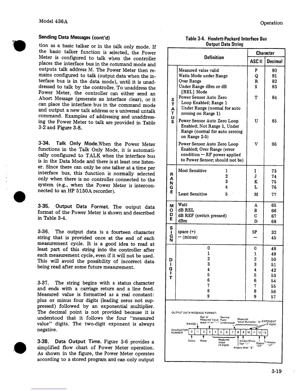
3-35.
Output
Data Format. The
output
data
format
of
the
Power Meter is shown and described
in Table 3-4.
3-36. The
output
data
is a fourteen character
string
that
is provided once
at
the
end
of
each
measurement cycle.
It
is a good idea to read
at
least
part
of
this
string
into
the controller
after
each measurement cycle, even if it will
not
be used.
This will avoid
the
possibility
of
incorrect
data
being read
after
some future measurement.
3-37. The string begins with
a
status character
and
ends with a carriage return
and
a line feed.
Measured
value
is
formatted
as
a
real constant:
plus
or
minus four digits (leading zeros
not
sup-
pressed) followed
by
an exponential multiplier.
The decimal
point
is
not
provided because
it
is
understood
that
it
follows the
four
"measured
value"
digits. The two-digit exponent is always
negative.
3-38.
Data
Output
Time. Figure 3-6 provides a
simplified flow
chart
of
Power Meter operation.
As
shown in
the
figure,
the
Power Meter operates
according
to
a stored program and can only
output
Operation
Table
3-4.
Hewlett-Packard
Interface
Bus
Output
Data
String
Character
Definition
ASCII
Decimal
Measured value valid
p
80
Watts Mode under Range
Q
81
Over Range
R
82
Under
Range dBm
or
dB
s
83
[REL] Mode
s
Power
Sensor
Auto
Zero
T
84
T
Loop Enabled; Range 1
A
Under
Range (normal for auto
T
zeroing
on
Range 1)
u
Power Sensor
Auto
Zero
Loop
u
85
s
Enabled; Not Range 1,
Under
Range (normal for
auto
zeroing
on Range 2-5)
Power Sensor
Auto
Zero
Loop
v
86
Enabled;
Over Range (error
condition - RF power applied
to
Power Sensor; should
not
be)
Most Sensitive
1
I
73
R
2
J
74
A
3
K
75
N
G
4
L
76
E
Least Sensitive 5
M 77
M
Watt
A 65
0
dBREL
B
66
D
dB
REF (switch pressed)
c
67
E
dBm
D
68
s
I
space(+)
SP
32
G
- (minus)
-
45
N
0 0
48
1
1
49
D
2
2
50
I
3
3
51
G
4
4
42
I
5 5
53
T
6
6
54
7
7
55
8
8
56
9
9
57
OUTPUT
DATA
MESSAGE
FORMAT:
Sign
of
Decimal
Measured
Value: Point
Measured
space(+)
or"-"
(understood) Value Multiplier:
10-EXPON.E~T
RANGE+
t
\'
~12dogotsl
~~~~~~TERr
0,
,
I
2
j
3
j
41
s
j
s
I
7
j
s
j
s
10j11j12j
13
I
t
f
Status Mode
Measured
lAl!ays
Minus
i
l.
Value s·gn
..
_..
Always Always
(4 Digits)
1
"CR"
"LF"
Always letter
"E"
3-19
 Loading...


