condition on the power lines in the A50 DC-DC Convereter. In this condition, though the
A50 power supplies, +24 V,+5VD, +18 V, +7.8 V, -7.8 V, and -18 V are shut down, the Fan
Power +24 V is still supplied to the fan. When the fan is not rotating, the shutdown circuit is
probably activated by the FAN LOCK signal missing.
Note
Once the A50 shutdown circuit is activated, the only way to reset the circuit is
turning the analyzer power o. Wait a minute after turning the analyzer o.
Then turn it on.
3. Check the A1 +5 VD LED
a. Remove the analyzer's bottom cover.
b. Turn the analyzer power on.
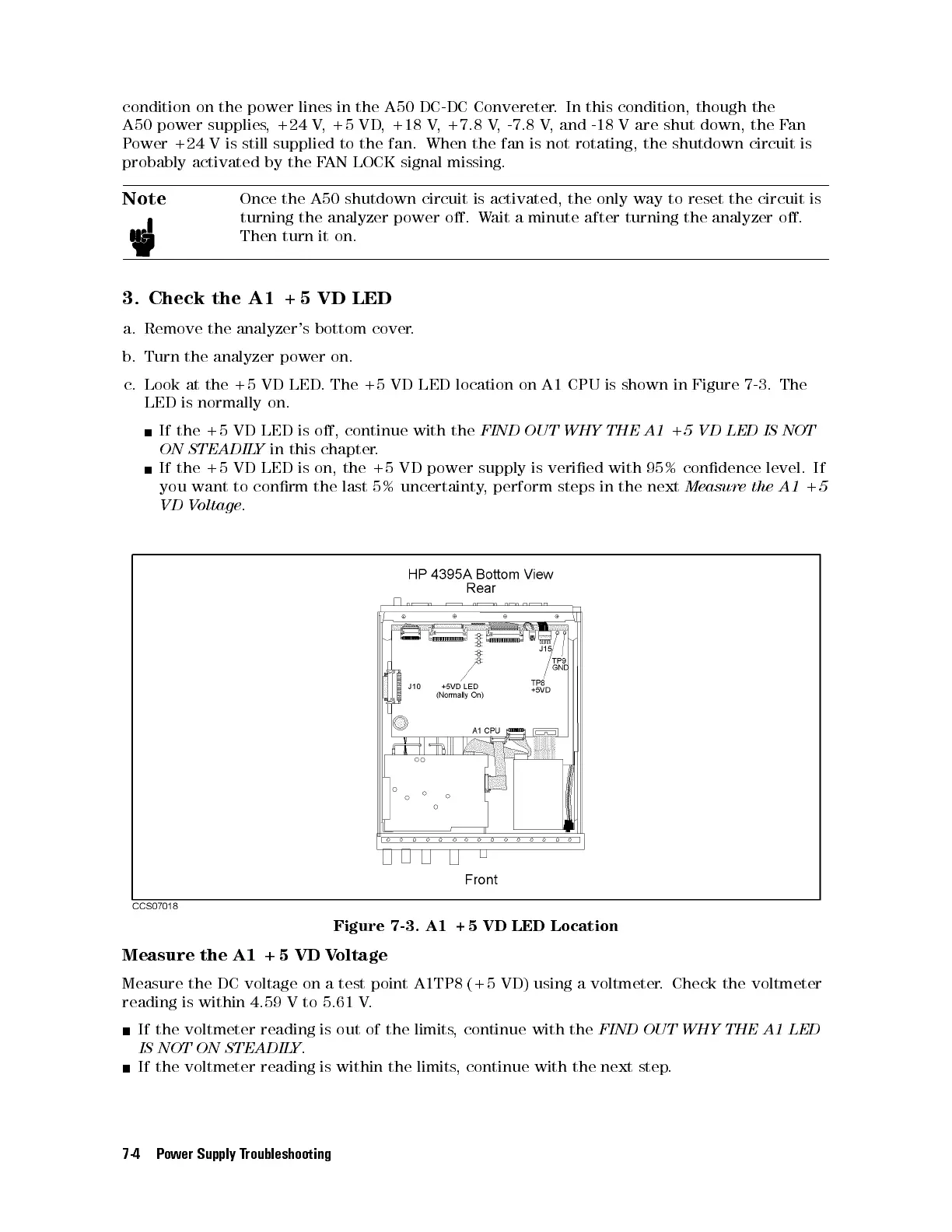
c. Look at the +5 VD LED. The +5 VD LED location on A1 CPU is shown in Figure 7-3. The
LED is normally on.
If the +5 VD LED is o, continue with the
FIND OUT WHY THE A1 +5 VD LED IS NOT
ON STEADILY
in this chapter.
If the +5 VD LED is on, the +5 VD power supply is veried with 95% condence level. If
you want to conrm the last 5% uncertainty, perform steps in the next
Measure the A1 +5
VD Voltage
.
Figure 7-3. A1 +5 VD LED Location
Measure the A1 +5 VD Voltage
Measure the DC voltage on a test point A1TP8 (+5 VD) using a voltmeter. Check the voltmeter
reading is within 4.59 V to 5.61 V.
If the voltmeter reading is out of the limits, continue with the
FIND OUT WHY THE A1 LED
IS NOT ON STEADILY
.
If the voltmeter reading is within the limits
, continue with the next step.
7-4 Power Supply Troubleshooting