2. Troubleshoot the A50 DC-DC Converter
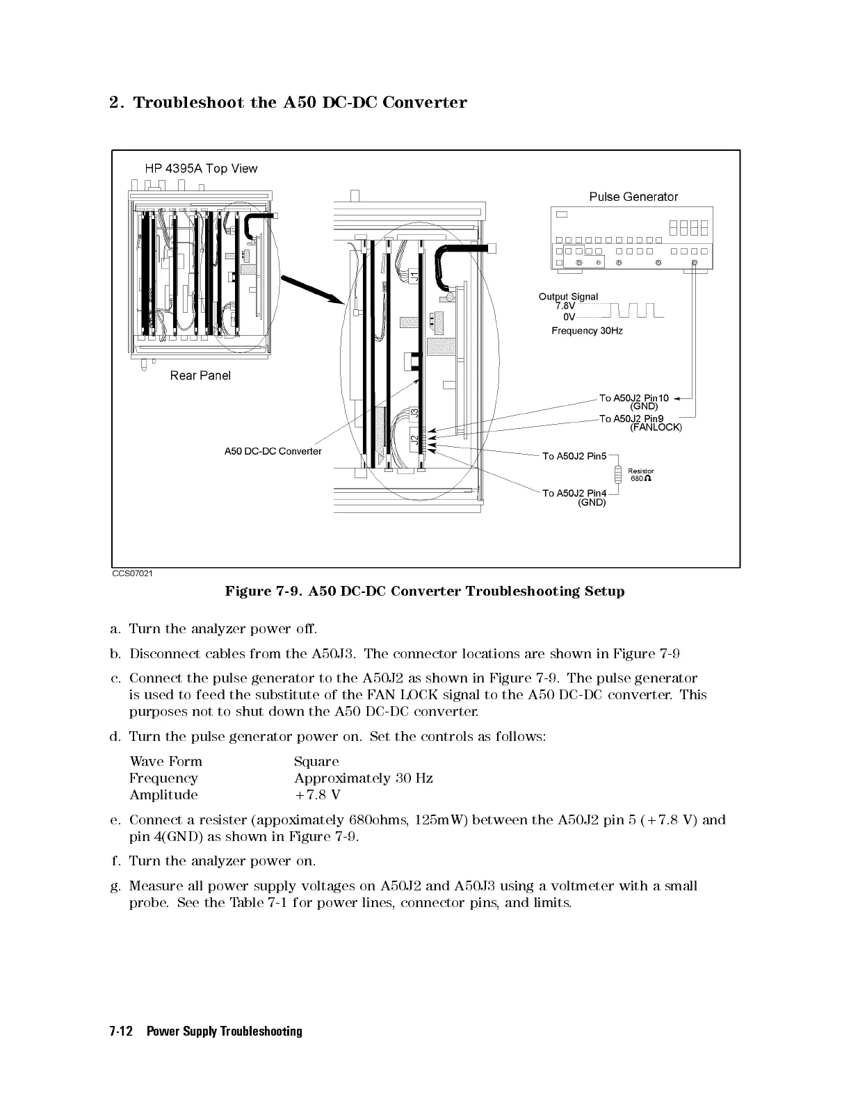
Figure 7-9. A50 DC-DC Converter Troubleshooting Setup
a. Turn the analyzer power o.
b. Disconnect cables from the A50J3. The connector locations are shown in Figure 7-9
c. Connect the pulse generator to the A50J2 as shown in Figure 7-9. The pulse generator
is used to feed the substitute of the FAN LOCK signal to the A50 DC-DC converter. This
purposes not to shut down the A50 DC-DC converter.
d. Turn the pulse generator power on. Set the controls as follows:
Wave Form Square
Frequency Approximately 30 Hz
Amplitude +7.8 V
e. Connect a resister (appoximately 680ohms, 125mW) between the A50J2 pin 5 (+7.8 V) and
pin 4(GND) as shown in Figure 7-9 .
f. Turn the analyzer power on.
g. Measure all power supply voltages on A50J2 and A50J3 using a voltmeter with a small
probe. See the Table 7-1 for power lines, connector pins, and limits.
7-12 Power Supply Troubleshooting
 Loading...


