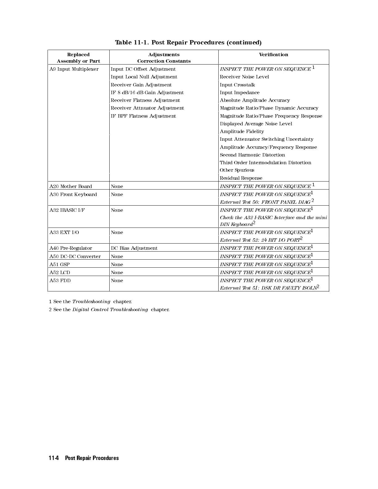
Table 11-1. Post Repair Procedures (continued)
Replaced
Assembly or Part
Adjustments
Correction Constants
Verication
A9 Input Multiplexer Input DC Oset Adjustment
INSPECT THE POWER ON SEQUENCE
1
Input Local Null Adjustment Receiver Noise Level
Receiver Gain Adjustment Input Crosstalk
IF 8 dB/16 dB Gain Adjustment Input Impedance
Receiver Flatness Adjustment Absolute Amplitude Accuracy
Receiver Attnuator Adjustment Magnitude Ratio/Phase Dynamic Accuracy
IF BPF Flatness Adjustment Magnitude Ratio/Phase Frequency Response
Displayed Average Noise Level
Amplitude Fidelity
Input Attenuator Switching Uncertainty
Amplitude Accuracy/Frequency Response
Second Harmonic Distortion
Third Order Intermodulation Distortion
Other Spurious
Residual Response
A20 Mother Board None
INSPECT THE POWER ON SEQUENCE
1
A30 Front Keyboard None
INSPECT THE POWER ON SEQUENCE
1
External Test 50: FRONT PANEL DIAG
2
A32 IBASIC I/F None
INSPECT THE POWER ON SEQUENCE
1
Check the A32 I-BASIC Interface and the mini
DIN Keyboard
2
A33 EXT I/O None
INSPECT THE POWER ON SEQUENCE
1
External Test 52: 24 BIT I/O PORT
2
A40 Pre-Regulator DC Bias Adjustment
INSPECT THE POWER ON SEQUENCE
1
A50 DC-DC Converter None
INSPECT THE POWER ON SEQUENCE
1
A51 GSP None
INSPECT THE POWER ON SEQUENCE
1
A52 LCD None
INSPECT THE POWER ON SEQUENCE
1
A53 FDD None
INSPECT THE POWER ON SEQUENCE
1
External Test 51: DSK DR FAULTY ISOLN
2
1
See the
Troubleshooting
chapter.
2
See the
Digital Control Troubleshooting
chapter.
11-4 Post Repair Procedures