b.
Press
4
Meas
5
,
NNNNNNNNNNNNNNNNNNNNNNNNNNNNNNNNNNNNNNNNN
ANALYZER TYPE
,
NNNNNNNNNNNNNNNNNNNNNNNNNNNNNNNNNNNNNNNNNNNNNNNNNN
NETWORK ANALYZER
,
4
Preset
5
to initialize the HP 4395A.
c. Initialize the multimeter. Then set the controls as follows:
Controls Settings
Measurement Function DC Volts Mode
Display Reading Value V Reading Value
Measurement Range Auto Range
NPLC 100
d. Set the HP 4395A and the multimeter to the rst column of Table 2-8
Table 2-8. DC Bias Level Test Settings
HP 4395A
DC Level
HP 4395A
DC Current Limit
Multimeter Range
(Auto Range)
0
40 V 100 mA 100 V
0
10 V 100 mA 10 V
0
4V 100 mA 10 V
0V 100 mA 1V
4V 100 mA 10 V
10 V 100 mA 10 V
40 V 100 mA 100 V
e. Wait for the multimeter reading to settle. Then record the reading in the calculation
sheet (\Multimeter Reading" column).
f. Change the setting of the HP 4395A and the multimeter in accordance with T
able 2-8 and
repeat step 1-e for each setting.
g. Calculate test results using the equation given in the calculation sheet. Record the test
results in the performance test record.
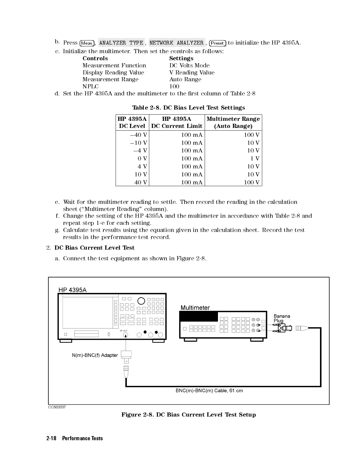
2.
DC Bias Current Level Test
a. Connect the test equipment as shown in Figure 2-8.
Figure 2-8. DC Bias Current Level Test Setup
2-18 Performance Tests