d.
Press
4
Cal
5
,
NNNNNNNNNNNNNNNNNNNNNNNNNNNNNNNNNNNNNNNNNNNN
CALIBRATE MENU
,
NNNNNNNNNNNNNNNNNNNNNNNNNN
RESPONSE
,
NNNNNNNNNNNNNN
THRU
to perform the response (THRU)
calibration. Wait for the completion of the sweep. Then press
NNNNNNNNNNNNNNNNNNNNNNNNNNNNNNNNNNNNNNNNN
DONE:RESPONSE
.
e. Set the step attenuator to the rst setting 10 dB in the second column of Table 2-16.
Table 2-16. B/R Dynamic Accuracy Test Settings 1
HP 4395A
Input Level
Step Attenuator HP 4395A
Source Power
0dB 10 dB 8 dBm
f. On the HP 4395A, press
4
Source
5
,
NNNNNNNNNNNNNNNNN
POWER
,
4
8
5
,
4
x1
5
to set the source power to the rst
setting in the third columns of Table 2-14.
g. Perform the following steps to measure the dynamic accuracy.
i.
Press
4
Trigger
5
,
NNNNNNNNNNNNNNNNNNNNNNNNNNNNNNNNNNNNNNNNNNNNNNNNNN
NUMBER OF GROUPS
,
4
5
5
,
4
x1
5
to make a sweep.Wait for the completion
of the sweep.
ii. Press
4
Marker
5
,
4
*
5
to move the channel 1 marker to 50.1 MHz.
iii. Record the channel 1 marker reading in the calculation sheet for the magnitude ratio
dynamic accuracy. Use the HP 4395A reading column corresponding to the input
level in the rst column of Table 2-16.
iv. Press
4
+
5
to move the channel 2 marker to 3 MHz.
v. Record the channel 2 marker reading directly in the performance test record. Use
the test result column of the phase measurement corresponding to the input level in
the rst column of Table 2-16.
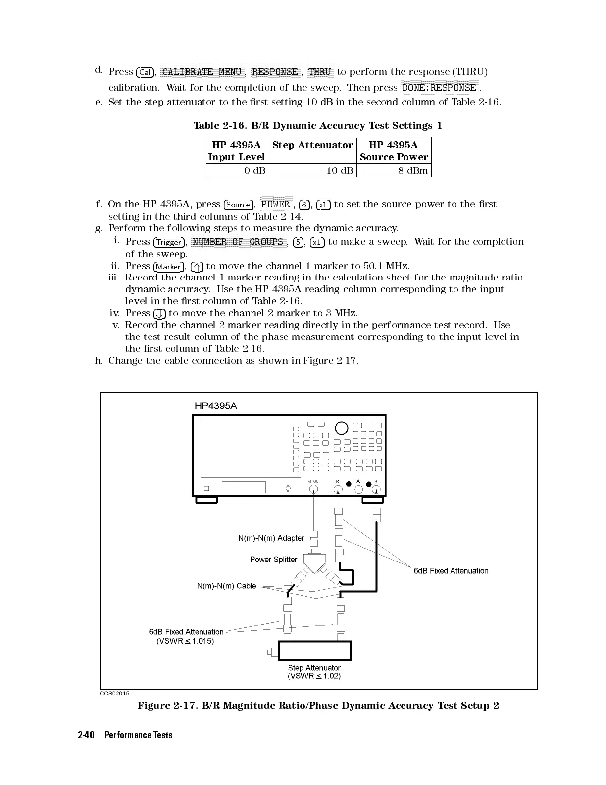
h. Change the cable connection as shown in Figure 2-17.
Figure 2-17. B/R Magnitude Ratio/Phase Dynamic Accuracy Test Setup 2
2-40 Performance Tests
 Loading...


