i. On the HP 4395A, set the controls as follows:
Control Settings Key Strokes
Source Power: 8 dBm
4
Source
5
,
NNNNNNNNNNNNNNNNN
POWER
,
4
8
5
,
4
x1
5
Active Channel: CH 1
4
Ch 1
5
Averaging Factor: 4
4
Bw/Avg
5
,
NNNNNNNNNNNNNNNNNNNNNNNNNNNNNNNNNNNNNNNNNNNNNNNNNN
AVERAGING FACTOR
,
4
4
5
,
4
x1
5
Active Channel: CH 2
4
Ch 2
5
Averaging Factor: 4
4
Bw/Avg
5
,
NNNNNNNNNNNNNNNNNNNNNNNNNNNNNNNNNNNNNNNNNNNNNNNNNN
AVERAGING FACTOR
,
4
4
5
,
4
x1
5
Input Attenuator R: 10dB
4
Scale Ref
5
,
NNNNNNNNNNNNNNNNNNNNNNNNNNNNNNNNNNNNNNNNNNNNNNN
ATTENUATOR MENU
,
NNNNNNNNNNNNNNNNNNNNNNN
ATTEN R
,
4
1
5
,
4
0
5
,
4
x1
5
Input Attenuator B: 0dB
4
Scale Ref
5
,
NNNNNNNNNNNNNNNNNNNNNNNNNNNNNNNNNNNNNNNNNNNNNNN
ATTENUATOR MENU
,
NNNNNNNNNNNNNNNNNNNNNNN
ATTEN B
,
4
0
5
,
4
x1
5
j. Set the step attenuator to 10 dB.
k.
Press
4
Cal
5
,
N
NNNNNNNNNNNNNNNNNNNNNNNNNNNNNNNNNNNNNNNNNNN
CALIBRATE MENU
,
N
NNNNNNNNNNNNNNNNNNNNNNNNN
RESPONSE
,
N
NNNNNNNNNNNNN
THRU
to perform the response (THRU)
calibration. Wait for the completion of the sweep. Then press
NNNNNNNNNNNNNNNNNNNNNNNNNNNNNNNNNNNNNNNNN
DONE:RESPONSE
.
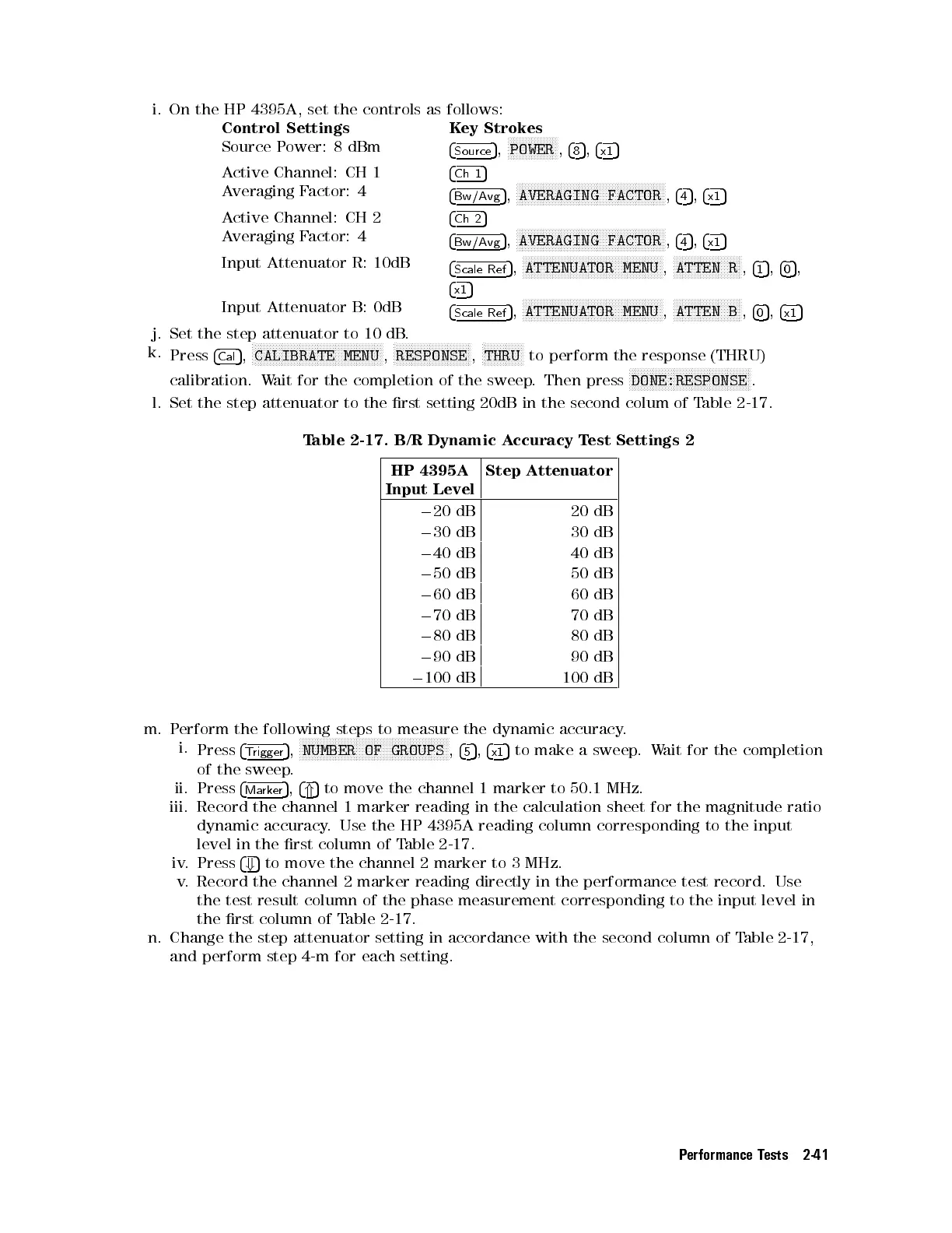
l. Set the step attenuator to the rst setting 20dB in the second colum of Table 2-17.
Table 2-17. B/R Dynamic Accuracy Test Settings 2
HP 4395A
Input Level
Step Attenuator
0
20 dB 20 dB
0
30 dB 30 dB
0
40 dB 40 dB
0
50 dB 50 dB
0
60 dB 60 dB
0
70 dB 70 dB
0
80 dB 80 dB
0
90 dB 90 dB
0
100 dB 100 dB
m. Perform the following steps to measure the dynamic accuracy
.
i.
Press
4
Trigger
5
,
NNNNNNNNNNNNNNNNNNNNNNNNNNNNNNNNNNNNNNNNNNNNNNNNNN
NUMBER OF GROUPS
,
4
5
5
,
4
x1
5
to make a sweep.Wait for the completion
of the sweep.
ii. Press
4
Marker
5
,
4
*
5
to move the channel 1 marker to 50.1 MHz.
iii. Record the channel 1 marker reading in the calculation sheet for the magnitude ratio
dynamic accuracy. Use the HP 4395A reading column corresponding to the input
level in the rst column of Table 2-17 .
iv. Press
4
+
5
to move the channel 2 marker to 3 MHz.
v. Record the channel 2 marker reading directly in the performance test record. Use
the test result column of the phase measurement corresponding to the input level in
the rst column of Table 2-17.
n. Change the step attenuator setting in accordance with the second column of Table 2-17 ,
and perform step 4-m for each setting.
Performance Tests 2-41
 Loading...


