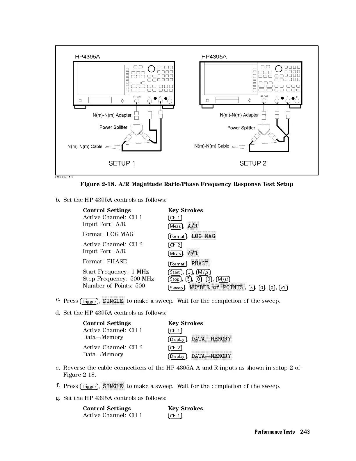
Figure 2-18. A/R Magnitude Ratio/Phase Frequency Response Test Setup
b. Set the HP 4395A controls as follows:
Control Settings Key Strokes
Active Channel: CH 1
4
Ch 1
5
Input Port: A/R
4
Meas
5
,
NNNNNNNNNNN
A/R
Format: LOG MAG
4
Format
5
,
NNNNNNNNNNNNNNNNNNNNNNN
LOG MAG
Active Channel: CH 2
4
Ch 2
5
Input Port: A/R
4
Meas
5
,
NNNNNNNNNNN
A/R
Format: PHASE
4
Format
5
,
N
NNNNNNNNNNNNNNNN
PHASE
Start Frequency: 1 MHz
4
Start
5
,
4
1
5
,
4
M/
5
Stop Frequency: 500 MHz
4
Stop
5
,
4
5
5
,
4
0
5
,
4
0
5
,
4
M/
5
Number of Points: 500
4
Sweep
5
,
NNNNNNNNNNNNNNNNNNNNNNNNNNNNNNNNNNNNNNNNNNNNNNNNNN
NUMBER of POINTS
,
4
5
5
,
4
0
5
,
4
0
5
,
4
x1
5
c.
Press
4
Trigger
5
,
NNNNNNNNNNNNNNNNNNNN
SINGLE
to make a sweep.Wait for the completion of the sweep.
d. Set the HP 4395A controls as follows:
Control Settings Key Strokes
Active Channel: CH 1
4
Ch 1
5
Data
!
Memory
4
Display
5
,
NNNNNNNNNNNNNNNNNNNNNNNNNNNNNNNNNNNNN
DATA
!
MEMORY
Active Channel: CH 2
4
Ch 2
5
Data
!
Memory
4
Display
5
,
NNNNNNNNNNNNNNNNNNNNNNNNNNNNNNNNNNNNN
DATA
!
MEMORY
e. Reverse the cable connections of the HP 4395A A and R inputs as shown in setup 2 of
Figure 2-18.
f.
Press
4
Trigger
5
,
NNNNNNNNNNNNNNNNNNNN
SINGLE
to make a sweep.Wait for the completion of the sweep.
g. Set the HP 4395A controls as follows:
Control Settings Key Strokes
Active Channel: CH 1
4
Ch 1
5
Performance Tests 2-43
 Loading...


