Data Math: DATA+MEM
4
Display
5
,
N
NNNNNNNNNNNNNNNNNNNNNNNNNNNNNNNNNNNNNNNNNNNNNN
DATA MATH [xxx]
,
N
NNNNNNNNNNNNNNNNNNNNNNNNN
DATA+MEM
,
N
NNNNNNNNNNNNN
GAIN
,
4
.
5
,
4
5
5
,
4
x1
5
Auto Scale
4
Scale Ref
5
,
NNNNNNNNNNNNNNNNNNNNNNNNNNNNNNNN
AUTO SCALE
Active Channel: CH 2
4
Ch 2
5
Data Math: DATA+MEM
4
Display
5
,
NNNNNNNNNNNNNNNNNNNNNNNNNNNNNNNNNNNNNNNNNNNNNNN
DATA MATH [xxx]
,
NNNNNNNNNNNNNNNNNNNNNNNNNN
DATA+MEM
,
NNNNNNNNNNNNNN
GAIN
,
4
.
5
,
4
5
5
,
4
x1
5
Auto Scale
4
Scale Ref
5
,
NNNNNNNNNNNNNNNNNNNNNNNNNNNNNNNN
AUTO SCALE
h.
Press
4
Ch 1
5
,
4
Search
5
,
NNNNNNNNNNN
MAX
and
4
Search
5
,
NNNNNNNNNNN
MIN
to move the channel 1 marker to the
maximum and minimum points on the trace. Compare the absolute values at the
maximum and minimum points.
i. Record the larger value in the performance test record (\Test Result" column for A/R
magnitude ratio).
j.
Press
4
Ch 2
5
,
4
Marker
!
5
,
NNNNNNNNNNNNNNNNNNNNNNNNNNNN
MKR
!
STOP
,
4
Cal
5
,
NNNNNNNNNNNNNN
MORE
,
NNNNNNNNNNNNNNNNNNNNNNNNNNNNNNNNNNNNNNNNNNNNNNNNNNNNNNNNNNNNNNNNN
ELECTRICAL DELAY MENU
,
NNNNNNNNNNNNNNNNNNNNNNNNNNNNNNN
MKR
!
DELAY
,
NNNNNNNNNNNNNNNNNNNNNNNNNNNNNNNNNNNNNNNNNNNNNNNNNN
ELECTRICAL DELAY
. Then press
4
*
5
or
4
+
5
and turn the RPG knob to vary the electrical
delay until the trace is in the most horizontal position.
k.
Press
NNNNNNNNNNNNNNNNNNNNNNNNNNNNNNNNNNNNNN
PHASE OFFSET
and enter the trace mean value using numeric keys. The trace
mean value is displayed as a marker statistic (mean) in the upper right-hand corner of
the display.
l.
Press
4
Search
5
,
NNNNNNNNNNN
MAX
and
4
Search
5
,
NNNNNNNNNNN
MIN
to move the channel 2 marker to the maximum
and minimum points on the trace. Compare the absolute values at the maximum and
minimum points.
m. Record the larger value in the performance test record (\T
est Result" column for A/R
phase).
*
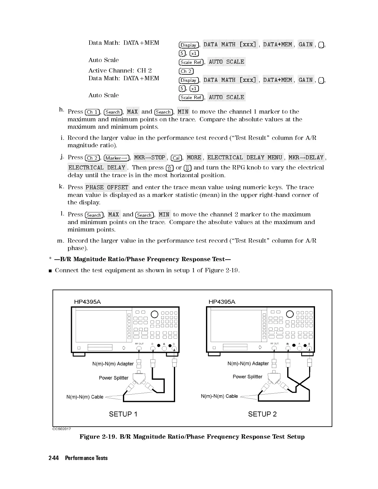
|B/R Magnitude Ratio/Phase Frequency Response Test|
Connect the test equipment as shown in setup 1 of Figure 2-19 .
Figure 2-19. B/R Magnitude Ratio/Phase Frequency Response Test Setup
2-44 Performance Tests
 Loading...


