Procedure
1. Record the step attenuator 50 MHz calibration values in the calculation sheet (\Calibration
Value" column).
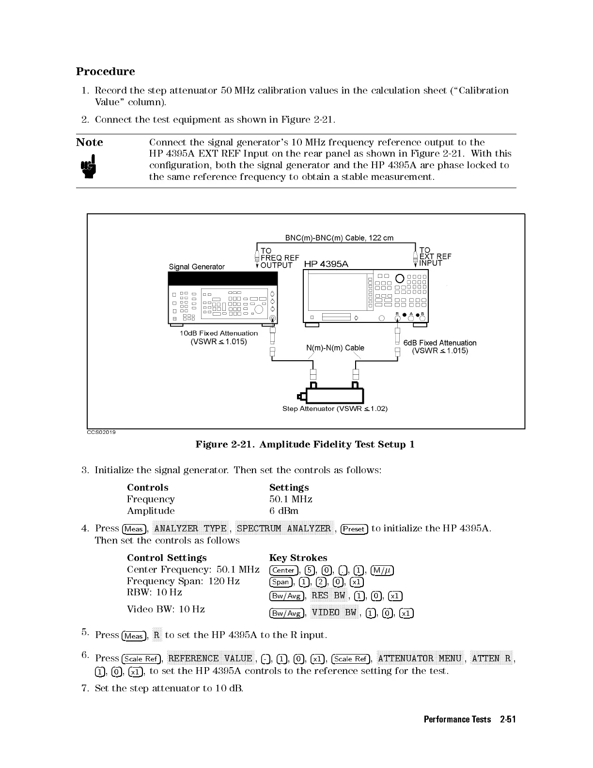
2. Connect the test equipment as shown in Figure 2-21.
Note
Connect the signal generator's 10 MHz frequency reference output to the
HP 4395A EXT REF Input on the rear panel as shown in Figure 2-21 . With this
conguration, both the signal generator and the HP 4395A are phase locked to
the same reference frequency to obtain a stable measurement.
Figure 2-21. Amplitude Fidelity Test Setup 1
3. Initialize the signal generator. Then set the controls as follows:
Controls Settings
Frequency 50.1 MHz
Amplitude 6 dBm
4. Press
4
Meas
5
,
NNNNNNNNNNNNNNNNNNNNNNNNNNNNNNNNNNNNNNNNN
ANALYZER TYPE
,
NNNNNNNNNNNNNNNNNNNNNNNNNNNNNNNNNNNNNNNNNNNNNNNNNNNNN
SPECTRUM ANALYZER
,
4
Preset
5
to initialize the HP 4395A.
Then set the controls as follows
Control Settings Key Strokes
Center Frequency: 50.1 MHz
4
Center
5
,
4
5
5
,
4
0
5
,
4
.
5
,
4
1
5
,
4
M/
5
Frequency Span: 120 Hz
4
Span
5
,
4
1
5
,
4
2
5
,
4
0
5
,
4
x1
5
RBW: 10 Hz
4
Bw/Avg
5
,
N
NNNNNNNNNNNNNNNNNNN
RES BW
,
4
1
5
,
4
0
5
,
4
x1
5
Video BW: 10 Hz
4
Bw/Avg
5
,
NNNNNNNNNNNNNNNNNNNNNNNNNN
VIDEO BW
,
4
1
5
,
4
0
5
,
4
x1
5
5.
Press
4
Meas
5
,
NNNNN
R
to set the HP 4395A to the R input.
6.
Press
4
Scale Ref
5
,
N
NNNNNNNNNNNNNNNNNNNNNNNNNNNNNNNNNNNNNNNNNNNNNN
REFERENCE VALUE
,
4
-
5
,
4
1
5
,
4
0
5
,
4
x1
5
,
4
Scale Ref
5
,
N
NNNNNNNNNNNNNNNNNNNNNNNNNNNNNNNNNNNNNNNNNNNNNN
ATTENUATOR MENU
,
N
NNNNNNNNNNNNNNNNNNNNNN
ATTEN R
,
4
1
5
,
4
0
5
,
4
x1
5
, to set the HP 4395A controls to the reference setting for the test.
7. Set the step attenuator to 10 dB
.
Performance Tests 2-51
 Loading...


