8. Perform the following steps to measure the amplitude delity.
a.
On the HP 4395A, press
4
Search
5
,
NNNNNNNNNNN
MAX
to move the marker to the peak of the carrier.
b. On the signal generator, adjust the amplitude until the HP 4395A marker reads
0
20 dB
6
0.1 dB.
c.
On the HP 4395A, press
4
Trigger
5
,
N
NNNNNNNNNNNNNNNNNNN
SINGLE
to make a sweep.Wait for the completion of
the sweep.
d.
Press
4
Search
5
,
NNNNNNNNNNN
MAX
,
4
Marker
5
,
NNNNNNNNNNNNNNNNNNNNNNNNNNNNNNNN
1MODE MENU
,
NNNNNNNNNNNNNNNNNNNNNNNNNNNNNNNN
FIXED 1MKR
to place the delta reference
marker on the peak of the carrier (reference level of the amplitude delity).
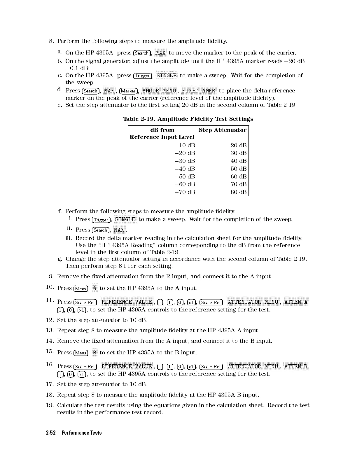
e. Set the step attenuator to the rst setting 20 dB in the second column of Table 2-19 .
Table 2-19. Amplitude Fidelity Test Settings
dB from
Reference Input Level
Step Attenuator
0
10 dB 20 dB
0
20 dB 30 dB
0
30 dB 40 dB
0
40 dB 50 dB
0
50 dB 60 dB
0
60 dB 70 dB
0
70 dB 80 dB
f. Perform the following steps to measure the amplitude delity
.
i.
Press
4
Trigger
5
,
NNNNNNNNNNNNNNNNNNNN
SINGLE
to make a sweep.Wait for the completion of the sweep.
ii.
Press
4
Search
5
,
NNNNNNNNNNN
MAX
.
iii. Record the delta marker reading in the calculation sheet for the amplitude delity
.
Use the \HP 4395A Reading" column corresponding to the dB from the reference
level in the rst column of Table 2-19.
g. Change the step attenuator setting in accordance with the second column of T
able 2-19.
Then perform step 8-f for each setting.
9. Remove the xed attenuation from the R input, and connect it to the A input.
10.
Press
4
Meas
5
,
N
NNNN
A
to set the HP 4395A to the A input.
11.
Press
4
Scale Ref
5
,
NNNNNNNNNNNNNNNNNNNNNNNNNNNNNNNNNNNNNNNNNNNNNNN
REFERENCE VALUE
,
4
-
5
,
4
1
5
,
4
0
5
,
4
x1
5
,
4
Scale Ref
5
,
NNNNNNNNNNNNNNNNNNNNNNNNNNNNNNNNNNNNNNNNNNNNNNN
ATTENUATOR MENU
,
NNNNNNNNNNNNNNNNNNNNNNN
ATTEN A
,
4
1
5
,
4
0
5
,
4
x1
5
, to set the HP 4395A controls to the reference setting for the test.
12. Set the step attenuator to 10 dB.
13. Repeat step 8 to measure the amplitude delity at the HP 4395A A input.
14. Remove the xed attenuation from the A input, and connect it to the B input.
15.
Press
4
Meas
5
,
NNNNN
B
to set the HP 4395A to the B input.
16.
Press
4
Scale Ref
5
,
NNNNNNNNNNNNNNNNNNNNNNNNNNNNNNNNNNNNNNNNNNNNNNN
REFERENCE VALUE
,
4
-
5
,
4
1
5
,
4
0
5
,
4
x1
5
,
4
Scale Ref
5
,
NNNNNNNNNNNNNNNNNNNNNNNNNNNNNNNNNNNNNNNNNNNNNNN
ATTENUATOR MENU
,
NNNNNNNNNNNNNNNNNNNNNNN
ATTEN B
,
4
1
5
,
4
0
5
,
4
x1
5
, to set the HP 4395A controls to the reference setting for the test.
17. Set the step attenuator to 10 dB.
18. Repeat step 8 to measure the amplitude delity at the HP 4395A B input.
19. Calculate the test results using the equations given in the calculation sheet. Record the test
results in the performance test record.
2-52 Performance Tests
 Loading...


