Section II
Paragraphs
2-25
to 2-28
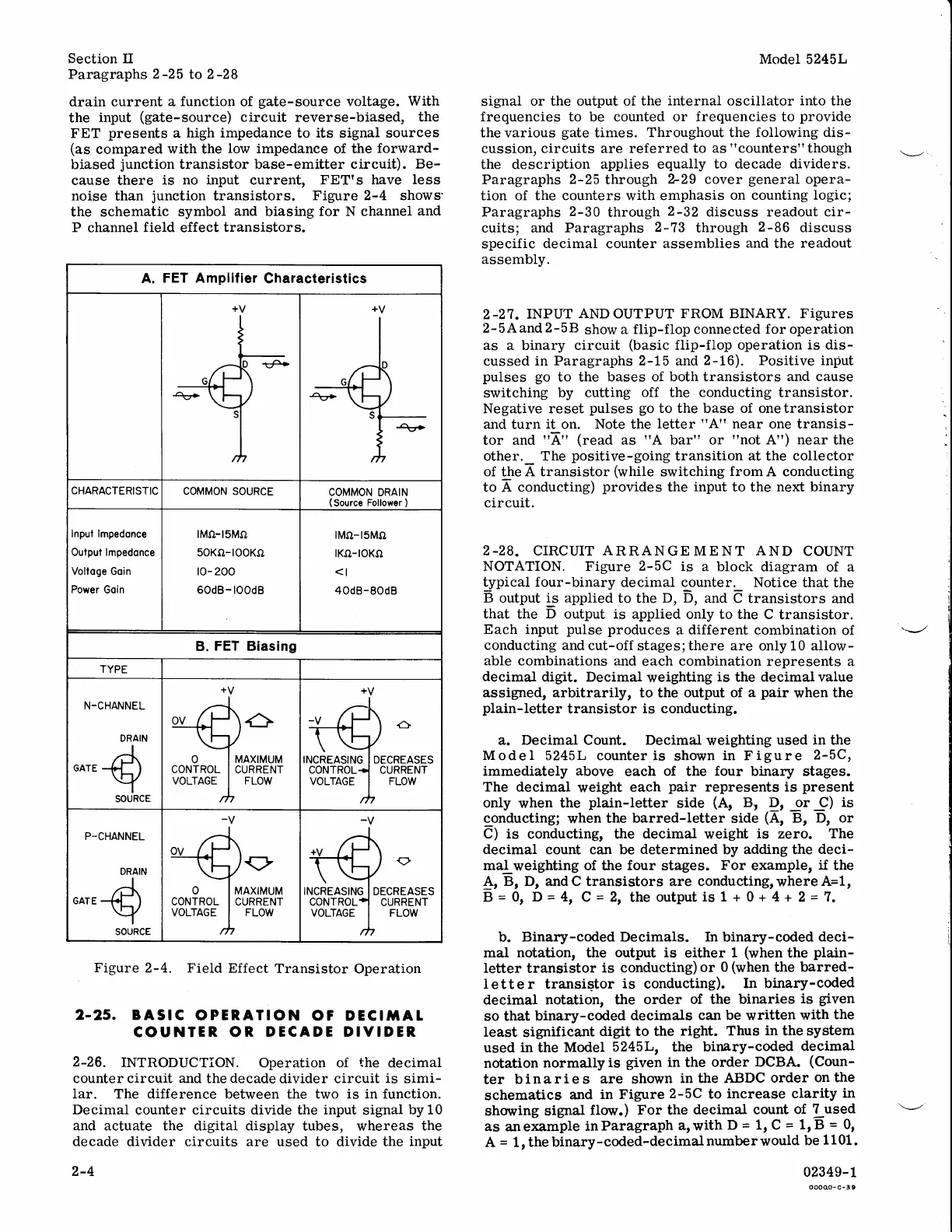
drain current a
function
of
gate-source
voltage.
With
the
input
(gate-source)
circuit reverse-biased,
the
FET
presents
a
high impedance to
its
signal sources
(as
compared
with the
low
impedance
of the
forward-
biased
junction
transistor base-emitter
circuit).
Be-
cause there
is no input current,
FETrs have
less
noise than
junction
transistors.
Figure 2-4 shows'
the schematic
symbol
and biasing for N channel
and
P
channel
field
effect
transistors.
Figure
2-4. Field
Effect
Transistor
Operation
2-25. BASIC
OPERATION
OF DEGIIIAT
COUNTER OR
DECADE DIYIDER
2-26.
INTRODUCTION.
Operation of
the
decimal
counter circuit and
the
decade
divider circuit
is
simi-
Iar. The difference between
the two
is in function.
Decimal
counter circuits divide the
input
signal
by
10
and actuate the digital display
tubes, whereas
the
decade divider circuits are used
to divide
the
input
2-4
Model
5245L
signal
or the output of
the
internal
oscillator
into
the
frequencies to
be
counted or
frequencies
to
provide
the
various
gate
times.
Throughout the following dis-
cussion, circuits are referred to
as
"counters"though
the description
applies equally
to decade dividers.
Paragraphs 2-25
through
2-29
cover
general
opera-
tion of
the counters
with
emphasis
on counting
logic;
Paragraphs
2-30
through
2-32
discuss readout cir-
cuits; and
Paragraphs
2-73
through
2-86
discuss
specific
decimal
counter
assemblies
and
the
readout
assembly.
2-27.INPUT
ANDOUTPUT
FROM BINARY.
Figures
2'5Aand
2-5B
show
a
flip-flop connected
for
operation
as a binary circuit
(basic
flip-flop operation
is
dis-
cussed in Paragraphs
2-15
and
2-16).
Positive
input
pulses go
to the bases
of both transistors
and cause
switching by
cutting off the
conducting
transistor.
Negative reset
pulses go
to the base of onetransistor
and
turn
it
on. Note the
letter
"A"
near
one transis-
tor and
"4"
(read
as
"A
bar"
or
"not
A") near
the
other._ The
positive-going
transition
at the collector
of
the
A transistor
(while
switching
from
A conducting
to A
conducting)
provides
the
input
to the next binary
circuit.
2.28.
CIRCUIT
ARRANGE
MENT
AND
COUNT
NOTATION. Figure
z-SC
is
a block
diagram
of a
blnicat
four-binary
decimal counter. Notice
that
the
B
output
i_s
applied to the
D, D,
and
C transistors
and
that
the
D
output is
applied only to
the C
transistor.
Each
input
pulse
produces
a
different
combination
of
conducting and
cut-off
stages;there are only 10 allow-
able combinations and
each combination represents
a
decimal
digit, Decimal
weighting
is
the
decimal value
assigned, arbitrarily, to the output of
a
pair
when
the
plain-Ietter
transistor
is conducting.
a. Decimal Count. Decimal
weighting
used in
the
Model 5245L counter is
shorvn
in Figure
2-5C,
immediately above
each
of
the
four
binary stages.
The
decimal
weight
each
pair
represents
is
present
only
when
the
plain-letter
side
(A,
Br
I,
jr
_9)
is
conducting;
when
the barred-Ietter
side
(A,
B, D, or
C)
is
conducting, the
decimal
weight
is
zero.
The
decimal count can be
determined
by
adding
the
deci-
mal
weighting
of the
four
stages.
For
example,
if
the
4,
B, D, andC
transistors
are conductingrwhereA=1,
B
=
0r
D
=
4t
C
=
2t
the
output
is 1 + 0 + 4
+ 2
=
1.
b. Binary-coded Decimals. In binary-coded deci-
mal
notation,
the
output is
either
1
(when
the
plain-
Ietter
transistor
is conducting)
or
0
(when
the
barred-
Ietter transiqtor
is
conducting).
In binary-coded
decimal
notation, the
order
of
the
binaries
is
given
so that
binary-coded
decimals
can be written with
the
least
significant
digit to the
right.
Thus
in
the system
used in the
Model
5245L, the binary-coded
decimal
notation
normally
is
given
in the
order
DCBA.
(Coun-
ter
binaries
are
shown
intheABDCorderonthe
schematics
and
in Figure
2-5C
to
increase clarity
in
shoring
signal
florv.)
For
the
decimal
count
of
7 used
as
anexatopte
inParagraph
arwith
D
=
1r C
=
1rE
=
0,
A
=
1, the
binary-coded-decimalnumberwould
be
1101.
02349-1
ooooo-c-39
A.
FET Amplifier
Characteristics
CHARACTERISTIC
COMMON SOURCE
COMMON
DRAIN
(Source
Follower
)
inpul lmpedonce
Outpul
lmpedonce
Voltoge
Goin
Power Goin
lMo-t5Mo
50KO-TOOKO
r0- 200
60dB-
toodB
lMo-l5Mo
lKo-roKo
<l
40dB-80d8
B.
FET Biasing
TYPE
N-CHANNEL
DRAIN
GATE
G
o
CONTROL
VOLTAGE
MAXIMUM
CURRENT
FLOW
INCREASING
DECREASES
CURRENT
FLOW
CONTROL
VOLTAGE
I
o
CONTROL
VOLTAGE
MAXIMUM
CURRENT
FLOW
INCREASING
DECREASES
CURRENT
FLOW
CONTROL
VOLTAGE

 Loading...


