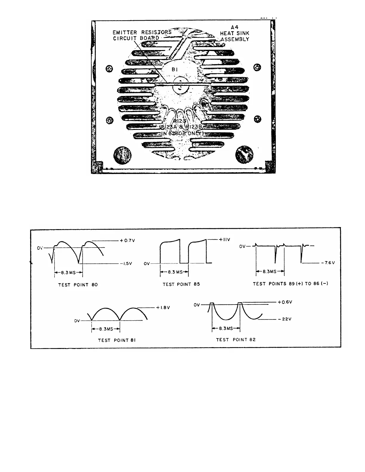
EasyManuals Logo

HP 6268B User Manual

HP 6268B
96 pages
To Next Page IconTo Next Page
To Previous Page IconTo Previous Page
Page #73 background imageLoading...
Page #73 background image
Figure 7-8.
A4 Heat Sink Assembly Component Location Diagram
(End view, assembly removed from supply.)
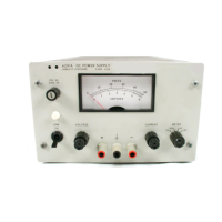
1. ALL WAVEFORMS TAKEN AT MAXIMUM RATED OUTPUT VOLTAGE, 230 VAC INPUT, NO LOAD CONNECTED AND
CURRENT CONTROLS FULLY CLOCKWISE.
2. SCOPE DC COUPLED AND REFERENCED TO TP103 (INBOARD SIDE OF CURRENT SAMPLING RESISTOR) UNLESS
OTHERWISE SHOWN.
3. FOR CLARITY, WAVEFORMS ARE NOT DRAWN TO SCALE.
Figure 7-9. Preregulator Control Circuit Waveforms
7-7
TM 11-6625-2958-14&P
NOTES

Other manuals for HP 6268B

Questions and Answers:

Question and Answer IconNeed help?

Do you have a question about the HP 6268B and is the answer not in the manual?

HP 6268B Specifications

General IconGeneral
BrandHP
Model6268B
CategoryPower Supply
LanguageEnglish

Related product manuals