Model 6960A
SERVICING
ETCHED
CIRCUIT
IOARDS
Section
V
Excessive
heat
or
pressure
can
lift
the
copper
strip
from
the
board.
Avoid
damage
by
using
a low
power
soldering
iron
(50
watts
maximum)
and following
these
instructions.
Copper
that
lifts
off
the
board
should
be
cemented
in
place
with a quick
drying
acetate
base
cement
having good
electrical
insulating
properties.
A
break
in
the
copper
should
be
repaired
by
soldering
a
short
length
of
tinned
copper
wire
across
the
break.
Use
only high
quality
rosin
core
solder
when
repairing
etched
circuit
boards.
NEVER USE PASTE FLUX.
After
soldering.
clean
off
any
excess
flux and
coat
the
repaired
area
with a high
quality
electrical
varnish
or
lacquer.
When
replacing components with multiple mounting pins such
as
tube
sockets,
electrolytic
capacitors,
and
potentiometers, it
will
be
necessary
to
lift each
pin
slightly. working around the components
several
times
until
it
is
free.
WARNING:
If
the
specific
instructions
outlined in
the
steps
below
regarding
etched
circuit
boards
without
eyelets
are
not followed.
extensive
damage
[Q
the etched circuit board will
result,
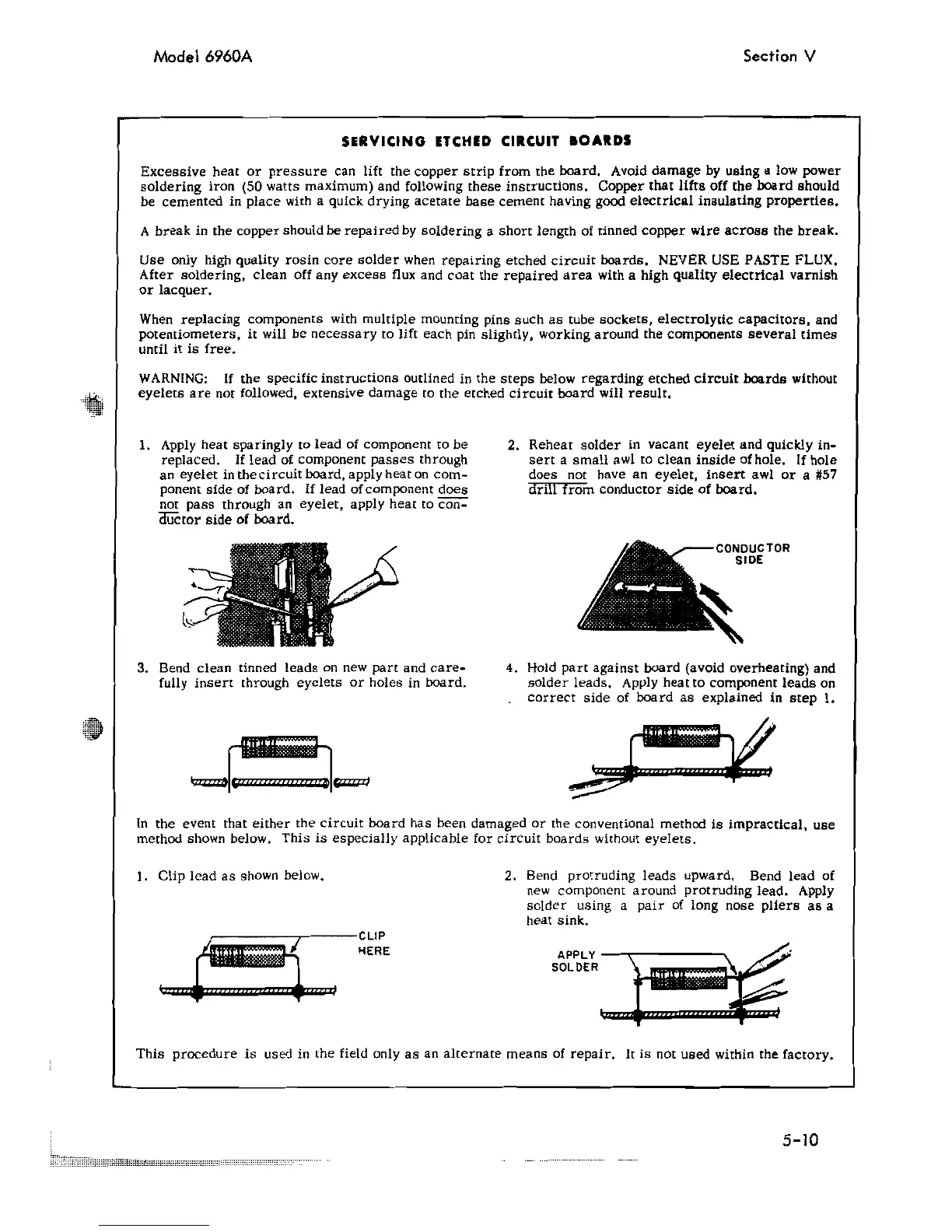
CONDUCTOR
SIDE
1. Apply
heat
sparingly
to
lead
of component
to
be
replaced.
If
lead
of component
passes
through
an
eyelet
in
the
circuit
board. apply heat
on
com
...
ponent
side
of
board.
If
lead
of
component
does
not
pass
through
an
eyelet,
apply
heat
to
Coil-
auctor
side
of
board.
3. Bend
clean
tinned
leads
on new part and
care-
fully
insert
through
eyelets
or
holes
in board.
2.
Reheat
solder
in
vacant
eyelet
and
quickly
in-
sert
a
small
awl
to
clean
inside
of
hole. If hole
does
not
have
an
eyelet,
insert
awl
or
a #57
drill
from
conductor
side
of
board.
4. Hold
part
against
board
(avoid
overheating)
and
solder
leads.
Apply
heat
to
component
leads
on
correct
side
of
board
as
explained
in
step
I.
In
the event that
either
the
circuit
board has been damaged or the conventional method
is
impractical,
use
method shown below. This
is
especially
applicable for
circuit
boards without
eyelets.
).
Clip
lead
as
shown below.
~,-----r---CLIP
~HERE
2. Bend
protruding
leads
upward. Bend
lead
of
new
component around protruding lead. Apply
solder
using a pair of long nose
pliers
as
a
heat sink.
...
,,~
SOLDER
#W9ill9Willill
~
This
procedure
is
used in the field only
as
an
alternate means
of
repair.
It
is
not used within the factory.
5-10