EL-MF877-00 Page 3
Template Revision B
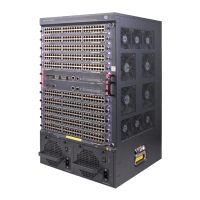
Figure 2 Rear of HP 7506
1. Unscrew the screws on mounting angle 2, and then remove mounting angle 2;
2. Unscrew the screws on cabling rack 3, and then remove cabling rack 3 from mounting;
3. Unscrew the screws on front panel 4, and then remove front panel 4;
4. Unscrew the screws on front panel 5, and then remove front panel 5;
5. Unscrew the screws on blank panel 6, and then remove blank panel 6;
6. Unscrew the screws on power supply module 7, and then remove power supply module 7;
7. Unscrew the screws on blank panel 8, and then remove blank panel 8;
8. Unscrew the screws on fan module 9, and then remove fan module 9;
9. Remove film 10;
10. Unscrew the screws on rear cover plate 11, and then remove rear cover plate 11;
11. Remove all of the inner cables;
12. Unscrew the screws on PCB 12, and then remove PCB 12;
13. Remove plug 13;
14. Remove all of the labels;
15. Remove all of shielding fingers.
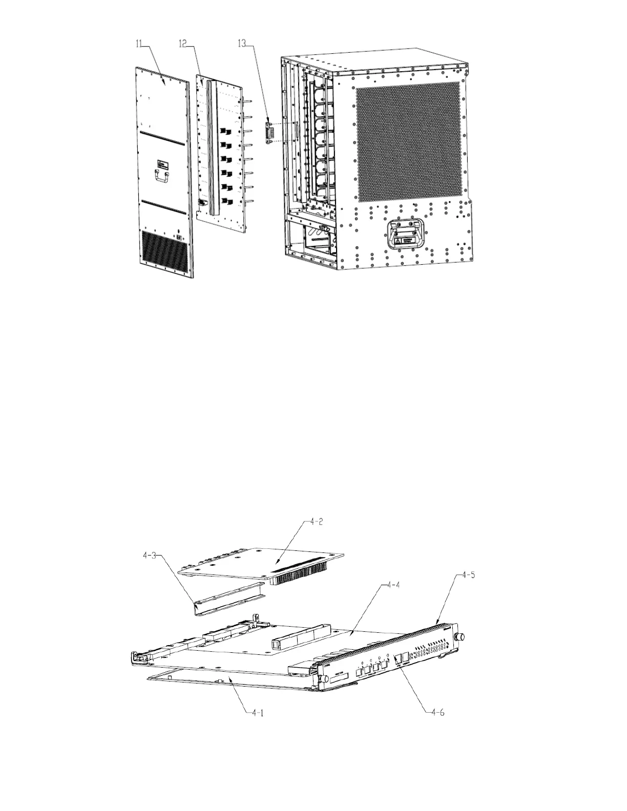
3.1.2 Guidance of treatments to module 4:
Figure 3 Treatments to module 4
 Loading...