Model
8642A/B
Installation
logic
levels
SIGNAL
GROUND
{
P
10
TWISTED
PAIR
WITH
11
PIO
TWISTED
PAIR
WITH
10
SHOULD
BE
GROUNDED
PIO
TWISTED
PAIR
WITH
9
NEAR
TERMINATION
PIO
TWISTED
PAIR
WITH
8
OF
OTHER
WIRE
OF
Pia
TWISTED
PAIR
WITH
7
TWISTED
PAIR
Pia
TWISTED
PAIR
WITH
6
ISOMETRIC
THREAD
M3.5
x
0.6
REN
0108
0107
0106
0105
SHIELD
-CONNECT
TO
ATN
EARTH
SRQ
GROUND
IFC
NOAC
NRFO
OAV
EOI
0104
010
3
010
2
010
1
24-PIN
MICRO-RIBBON
(SERIES
57)
CONNECTOR
The Hewlett-Packard Interface Bus logic levels are TTL compatible, i.e., the true
(1)
state is 0.0 Vdc to +0.4
Vdc and the false
(0)
state is 2.5 Vdc to
+5
Vdc.
Programming
and
Output
Data
Format
Refer to Section
III,
"Operation".
Mating
Connector
HP 1251-0293; Amphenol 57-30240.
Mating
Cables
Available
HP
10631A, 1 metre (3.3 ft.),
HP
10631B, 2 metres (6.6 ft.)
HP
10631C, 4 metres (13.2 ft.), HP 106310, 0.5 metres (1.6 ft.)
Cabling
Restrictions
1.
A Hewlett-Packard Interface Bus system may contain no more than 2 metres (6.6 ft.)
of
connecting cable
per instrument.
2.
The maximum accumulative length
of
connecting cable for any Hewlett-Packard Interface Bus system is
20 metres (65.6
ft.).
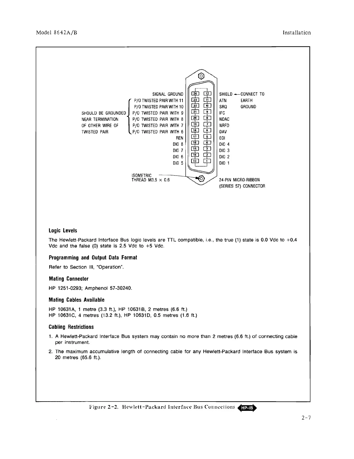
Figure
2-2.
Hcwldt-Packard
Interfa('c
Bus
CUllnl'cliollS
~
2-7

 Loading...


