General
Information
Model 864
2A/B
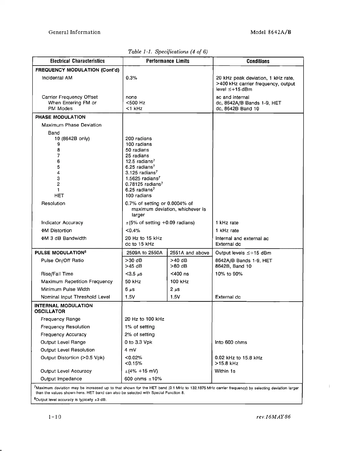
Table 1-1. Specifications (4
of
6)
Electrical
Characteristics
Performance
Limits
Conditions
FREQUENCY MODULATION (Cont'd)
Incidental
AM
0.3%
20 kHz peak deviation, 1 kHz rate,
>400
kHz carrier frequency, output
level :$+15 dBm
Carrier Frequency Offset
none
ac and internal
When Entering FM
or
<500
Hz
dc, 8642AfB Bands 1-9, HET
PM
Modes
<1
kHz
dc, 8642B Band
10
PHASE MODULATION
Maximum Phase Deviation
Band
10 (8642B only) 200 radians
9 100 radians
8 50 radians
7 25 radians
6
12.5 radians
7
5
6.25 radians
7
4 3.125 radians
7
3
1.5625 radians
7
2 0.78125 radians
7
1 6.25 radians
7
HET 100 radians
Resolution 0.7% of setting
or
0.0004% of
maximum deviation, whichever is
larger
Indicator Accuracy ±(5%
of
setting +0.09 radians)
1 kHz rate
<l>M
Distortion
<0.4%
1 kHz rate
<l>M
3
dB
Bandwidth
20
Hz
to
15 kHz
Internal and external ac
dc to 15 kHz
External dc
PULSE MODULATION8
2509A to 2550A
2551A and above Output levels :$+15 dBm
Pulse On/Off Ratio
>30
dB
>40
dB
8642AfB Bands 1-9, HET
>45
dB
>80
dB 8642B, Band 10
Rise/Fall Time <3.5
jLS <400 ns 10% to 90%
Maximum Repetition Frequency
50
kHz
100 kHz
Minimum Pulse Width
6
jLS
2 jLS
Nominal Input Threshold Level
1.5V
1.5V External
dc
INTERNAL MODULATION
OSCILLATOR
Frequency Range 20 Hz
to
100 kHz
Frequency Resolution 1 %
of
setting
Frequency Accuracy 2% of setting
Output Level Range
o to 3.3 Vpk Into 600 ohms
Output Level Resolution 4
mV
Output Distortion (>0.5 Vpk) <0.02%
0.02 kHz to 15.8 kHz
<0.15%
>15.8 kHz
Output Level Accuracy ±(4%
+15
mV)
Within
1s
Output Impedance
600 ohms ± 1 0%
7Maximum deviation may
be
increased up to that shown for the HET band
(0.1
MHz to 132.1875 MHz carrier frequency)
by
selecting deviation larger
than the values shown here. HET band
can
also be selected with Special Function
8.
80
u
tput level accuracy is typically
±3
dB.
1-10
rev.16MAY86
 Loading...