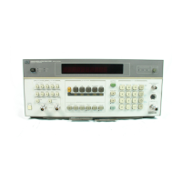
Model
8901B
Service
Since the notch-filter frequency
is
fixed at either
1
kHz
or
400
Hz,
the signal being measured should be
within
*5%
of the selected frequency. Amplifier
1
and Amplifier
2,
which together have an overall gain
of
0,
20,
or
40
dF3,
are programmed to provide an optimum level to the RMS-to-DC Converter. The
voltage measured when the Notch Select Switch
is
set
to
include the Notch Filters is the numerator
in the distortion calculation. The voltage measured when the Notch Select Switch is set
to
bypass the
Notch Filters
is
the denominator in the distortion calculation. Since the signal minus
its
fundamental
is often noisy, the signal to the Voltmeter is filtered by an active Ripple Filter to smooth the voltage
readings. Special Function
29
puts the instrument
in
the SINAD measurement mode. The SINAD
measurement
is
the same as the Audio Distortion measurement except that the reciprocal of the
distortion measurement
is
displayed.
To calculate the frequency of an internal
or
external audio signal, the Controller counts
signals
from
both the Audio Counter and the main Counter (on Service Sheet
BD5).
First, the analog audio signal
is conditioned by the Schmitt Trigger
to
make
it
compatible with the digital circuits that follow. To
begin the count, the Controller resets Counter Stages
1-4.
At this time, Count/Pulse Switch
2
is
set
to receive the output from Counter Stage
2
and the Output Switch
is
closed. Count/Pulse Switch
1
is
readied but not closed until the next pulse from the Schmitt Trigger triggers the Counter Gate Control
and sets Count/Pulse Switch
1
to
receive pulses from the Schmitt Trigger. The Counter Stages
1-4
now begin counting pulses from the Schmitt Trigger. Overflows from Stage
4
(every
65 536
counts) are
counted by the Controller via the Output Switch and Instrument
Bus.
Coincident with the closing of Count/Pulse Switch
1,
the Voltmeter/Audio Gate (on Service Sheet
BD5)
closes and the main Counter begins counting the
10
MHz
time base reference. After
100
ms, the
Controller enables the Counter Gate Control to respond
to
the next pulse from the Schmitt Trigger.
When the pulse arrives,
it
triggers the Counter Gate Control
to
open Count/Pulse Switch
1
and the
Voltmeter/Audio Gate via the Stop Count Buffer.
If
no pulse
is
received from the Schmitt Trigger after
a fixed time, the count sequence
is
aborted.
The count from Audio Counter Stages
1-4
is
read back in
two
steps. First, the Controller reads back
the count of Stages
3
and
4
by sending a series of pulses into Stage
3
via CountPulse Switch
2,
looking for the overflow from Stage
4.
By knowing the number of pulses sent to Stage
3,
the Controller
can calculate the accumulated count. Next, the Controller sends
255
pulses
to
Stages
3
and
4
to
fill
them, sets Count/Pulse Switch
2
to the output of Stage
2,
and
sends a series of pulses
to
Stage
1
via
Count/Pulse Switch
1
while looking for an overflow from Stage
4.
Again, by knowing the number of
pulses sent to Stage
1,
the Controller can calculate the accumulated count from Stages
1
and
2.
The
count from the main Counter
is
also read back by the Controller. Knowing the counts of the Audio
and main Counters (including overflows), the Controller calculates and displays the signal frequency.
Service Sheet BD4
8D-39


 To Next Page
 Loading...