9030/40 Peripherals 7-5
To configure the
GPIO card:
1.
Install jumpers
in
WI,
W2,
and
W3,
according to whether 5-volt or 12-volt logic levels are to
be used.
2.
Set the card's switches
for
proper operation.
3.
If
necessary, increase the delays on the card as
follows:
Two one-shots (EI5) on the GPIO card generate the write delay
and
the internal handshake
delay. The write delay one-shot provides approximately
100 nsec for the output data to
settle. When extra-long cables are used, or when the peripheral device requires additional
settling time
for
the data, the delay can be increased by adding a capacitor between pins 1
and 4 of the socket at E16
The formula
for
selecting the capacitor value
is:
C = (T-100)/1.5
where
C = additional capacitance
(in
pf)
T = total time delay required
in
nsec
The internal delay one-shot provides a delay of approximately 3 usec between the assertion
of
PCNTL and the assertion of
FLAG.
The delay can be increased by adding a capacitor
between pins 5 and 8 of the socket at E16.
The formula
for
the value of the capacitor
is:
C = (T-3000)/3
where
C = additional capacitance
(in
pf)
T = total time delay required
(in
nsec)
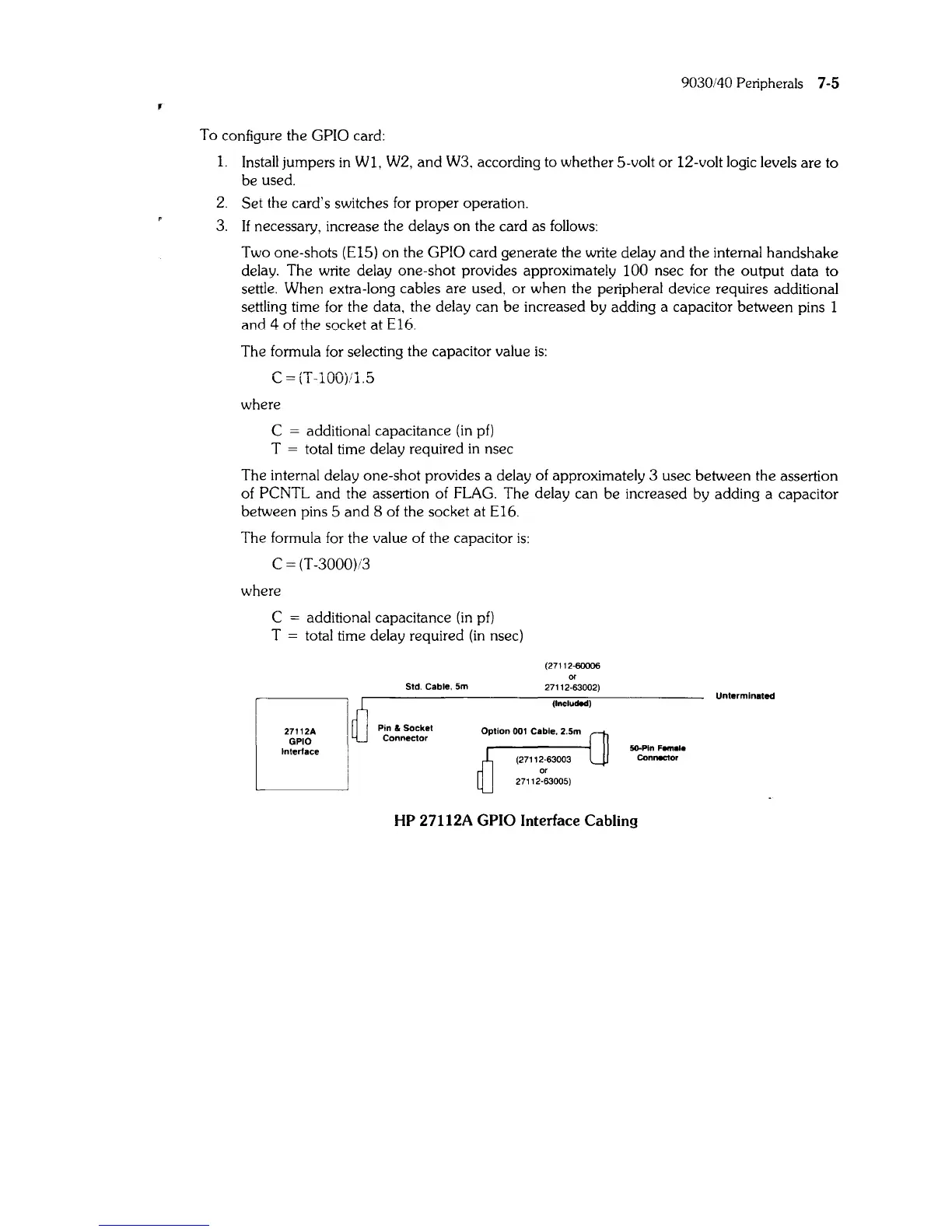
27112A
GPIO
Interface
Std. Cable,
Sm
Pin &
Socket
Connector
(27112-60006
or
27112·63002)
(Included)
SO-Pln
Female
Connector
HP 27112A GPIO Interface Cabling
Unterminated