2
CPU Upgrade
CPU Configuration Rules
Anti-Static Mat
The anti-static mat can be either the conductive bag, the ESD sheet, or the ESD foam pad. The anti-static
mat does not have to be connected to the cabinet. It should be placed close to the computer while
performing the upgrade tasks.
CPU Configuration Rules
The rules for adding a CPU to a system are as follows:
1. The computer must have a CPU installed in slot 0 (zero).
2. All additional CPUs are added in sequential order (1, 2,... and so on).
Once the CPU card is added to the computer, it is automatically configured into the system during the
computer power on selftest process.
CPU Location
The CPU slots for both the HP 3000/9x9KS and HP 9000/K2xx and K4xx SPUs are the same. Figure 1-1
and Figure 1-2 shows the CPU locations for these systems. Figure 1-1, front view, shows the system with
the front bezel and bulkheads (or cover plates) removed. Figure 1-2, rear view, shows the system with the
back cover removed.
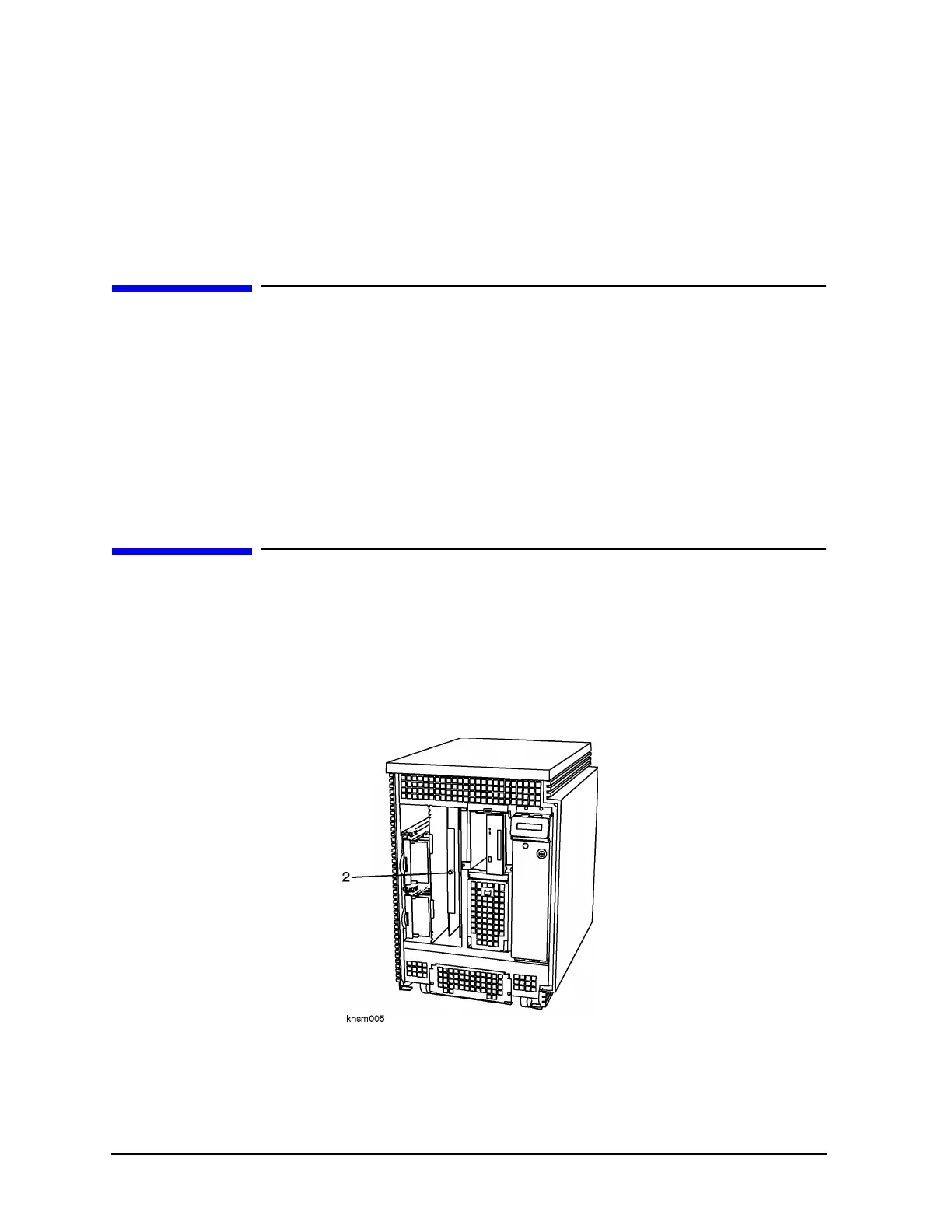
Figure 1-1 CPU Location, Front View (All Models)
Item 2 shows the location of CPU slots 0 and slot 1. Slot 0 is located next to the power monitor and Slot
1 is located next to the peripheral cage.
 Loading...


