Voltage Isolation Diagrams
6-16 Wiring Diagrams and Electrical Data June 1999
Voltage Isolation Diagrams
Use the following voltage isolation diagrams to locate the presence or loss of proper DC
potentials within the printer. Simplex circuit are shown first, followed by duplex circuits.
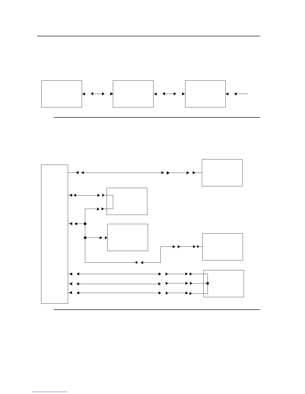
Figure 6-1. (Simplex) -12 Vdc Circuits
Figure 6-2. (Simplex) +5 Vdc Circuit
DC Power
Supply
IGS
Board
J/P8-8
J/P32-3
J/P88-32
J/P74-32
J/P73-4
Signal Interface
Board
External
Attachment
Connector
PCL Board
DC Power
Supply
IGS Board
J/P8-1
Operator Panel
Board
Printhead
Board
Disk Drive
J/P77-4
J/P8-10
J/P32-5
J/P8-14
J/P91-5
J/P7-1
J/P7-2
J/P7-3
J/P94-1
J/P90-1 J/P42-1
J/P27-1
J/P27-2
J/P27-3
J/P32-6