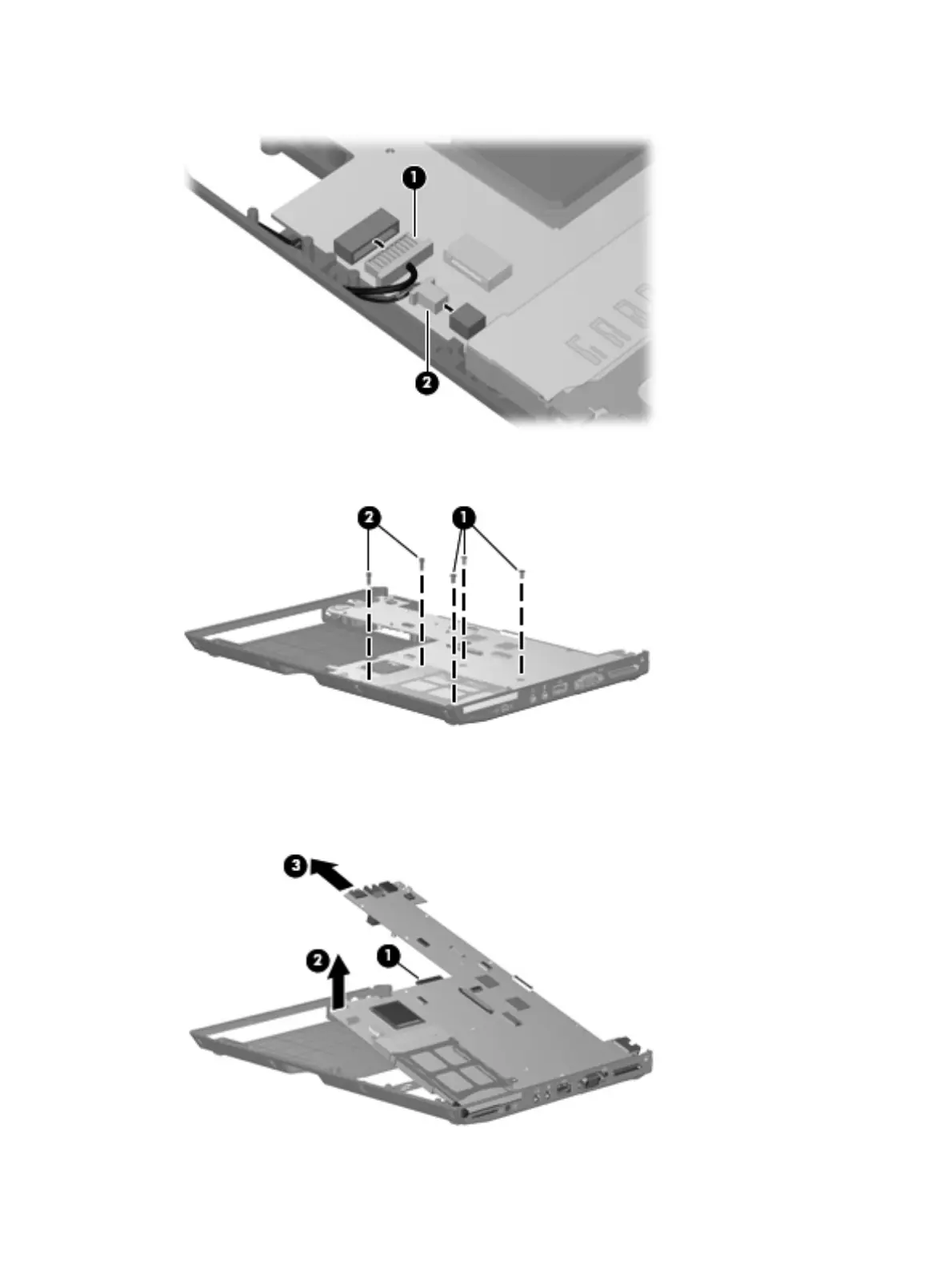
6. Disconnect the front LED board cable (1) and the speaker cable (2) from the system board.
7. Remove the three Torx T8M2.5×7.0 screws (1) and the two Phillips PM2.0×10.0 screws (2) that
secure the system board to the base enclosure.
8. Use the optical drive connector (1) to lift the left side of the system board (2) until it rests at an
angle.
9. Remove the system board (3) by sliding it away from the base enclosure at an angle.
72 Chapter 4 Removal and replacement procedures
 Loading...