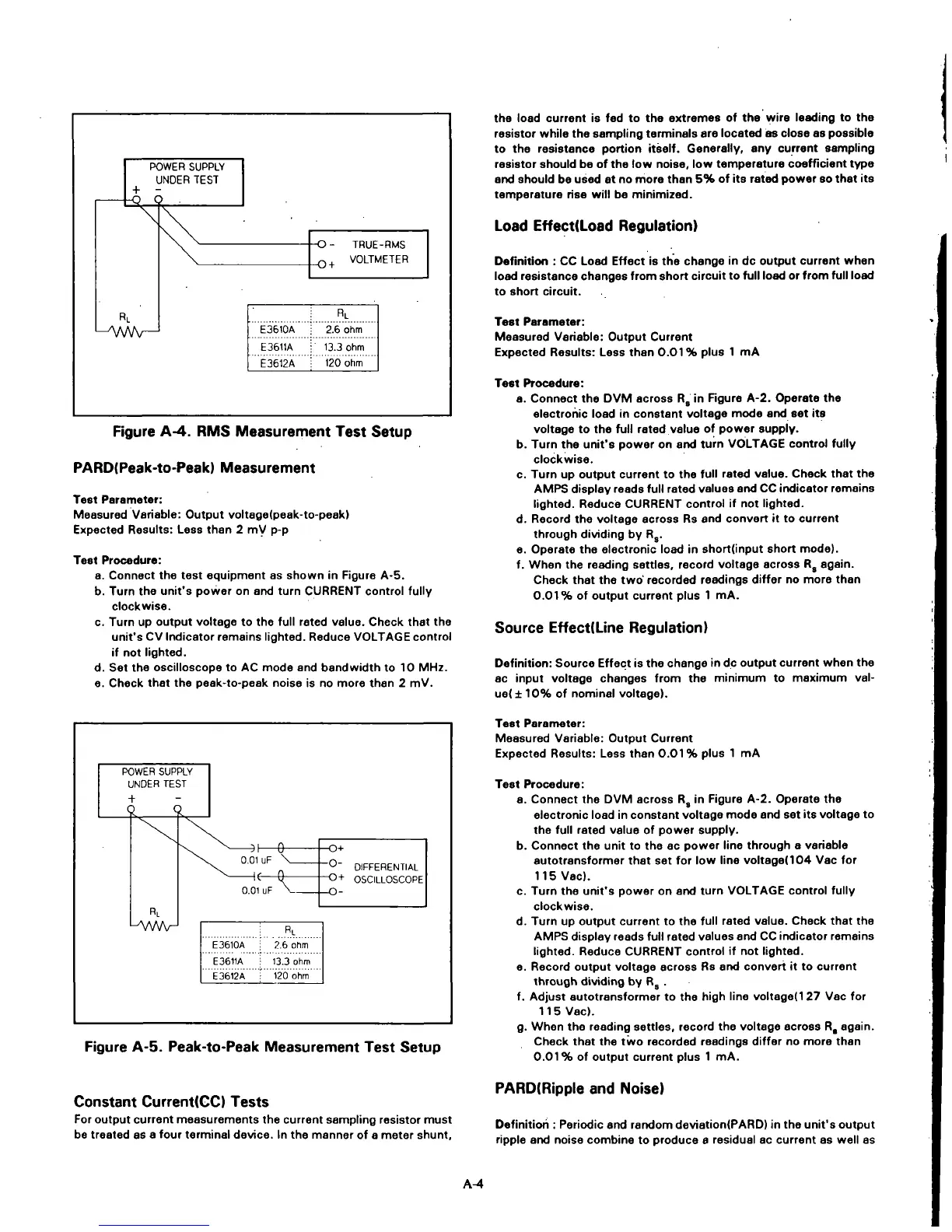
POWER SUPPLY
UNDER TEST
-1-
-
^
RL
L^VWV—
1
\
E3610A
E3611A
E3612A
-O - TRUE
_(-,,
VOLB
RL
2.6 ohm
13.3 ohm
120 ohm
-RMS
/lETER
Figure A-4. RMS Measurement Test Setup
PARD(Peak-to-Peak) Measurement
Test Parameter:
Measured Variable: Output voltage(peak-to-peak)
Expected Results: Less than 2 mV p-p
Test Procedure:
a. Connect the test equipment as shown in Figure A-5.
b. Turn the unit's power on and turn CURRENT control fully
clockwise.
c. Turn up output voltage to the full rated value. Check that the
unit's CV Indicator remains lighted. Reduce VOLTAGE control
if not lighted.
d.
Set the oscilloscope to AC mode and bandwidth to 10 MHz.
e. Check that the peek-to-peak noise is no more than 2 mV.
the load current is fed to the extremes of the wire leading to the
resistor while the sampling terminals are located as close as possible
to the resistance portion itself. Generally, any current sampling
resistor should be of the low noise, low temperature coefficient type
arxl should be used at no more than 5% of its rated power so that its
temperature rise will be minimized.
Load Effect(Load Regulation)
Definition : CC Load Effect is the change in dc output current when
load resistance changes from short circuit to full load or from full load
to short circuit.
Test Parameter:
Measured Variable: Output Current
Expected Results: Less than 0.01% plus 1 mA
Test Procedure:
a. Connect the DVM across R, in Rgure A-2. Operate the
electronic load in constant voltage mode and set its
voltage to the full rated value of power supply.
b. Turn the unit's power on and turn VOLTAGE control fully
clockwise.
c. Turn up output current to the full rated value. Check that the
AMPS display reads full rated values and CC indicator remains
lighted.
Reduce CURRENT control if not lighted.
d.
Record the voltage across Rs and convert it to current
through dividing by R,.
e. Operate the electronic load in short(input short mode).
f. When the reading settles, record voltage across R, again.
Check that the two' recorded readings differ no more than
0.01%
of output current plus 1 mA.
Source Effect(Line Regulation)
Definition:
Source Effect is the change in dc output current when the
ac input voltage changes from the minimum to maximum val-
ue( ± 10% of nominal voltage).
POWER SUPPLY
UNDER TEST
RL
LAAAAr-l
-^1—Q-
0.01 uF
0.01
uF V_
-O-i-
"O-
DIFFERENTIAL
-0+ OSCILLOSCOPE
-O-
RL
E3610A
E3611A
E 3612 A
2.6 ohm
• 13.3 ohm
• 120 ohm
Figure A-5. Peak-to-Peak Measurement Test Setup
Test Parameter:
Measured Variable: Output Current
Expected Results: Less than 0.01% plus 1 mA
Test Procedure:
a. Connect the DVM across R, in Figure A-2. Operate the
electronic load in constant voltage mode and set its voltage to
the full rated value of power supply.
b. Connect the unit to the ac power line through a variable
autotransformer that set for low line voltage(104 Vac for
115 Vac).
c. Turn the unit's power on and turn VOLTAGE control fully
clockwise.
d.
Turn up output current to the full rated value. Check that the
AMPS display reads full rated values and CC IrKlicator remains
lighted.
Reduce CURRENT control if not lighted.
e. Record output voltage across Rs and convert it to current
through dividing by R, .
f. Adjust autotransformer to the high line voItage(127 Vac for
115 Vac).
g.
When the reading settles, record the voltage across R, again.
Check that the two recorded readings differ no more than
0.01%
of output current plus 1 mA.
Constant Current(CC) Tests
For output current measurements the current sampling resistor must
be treated as a four terminal device. In the manner of a meter shunt.
PARD(Ripple and Noise)
Definitioii:
Periodic and rarxJom deviation(PARD) in the unit's output
ripple and noise combine to produce a residual ac current as well as
A-4