Do you have a question about the HP E3611A and is the answer not in the manual?
Instruction to verify the product is set to match the available line voltage before powering it on.
Details the requirement to connect the instrument chassis to an electrical ground for safety.
Warning against operating the instrument in the presence of flammable gases or fumes.
Explains the meaning of safety symbols like Warning and Caution used in the manual.
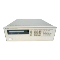
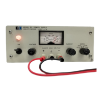
Provides a basic description of the HP E3610A, E3611A, and E3612A power supplies.
Details the input voltage/power requirements and output voltage/current ranges.
Specifies load/line regulation and ripple/noise levels for CV and CC modes.
Details temperature, transient response, drift, isolation, and meter accuracy.
Covers overload protection, terminals, cooling, weight, and characteristics.
Lists available options and explains instrument serial number identification.
Guide for incoming inspection, placement, and cooling requirements.
Details input power requirements and the importance of the power cord connection.
Procedure to verify the operational status of the power supply using front panel controls.
Steps to set up the power supply for constant voltage (CV) operation.
Steps to set up the power supply for constant current (CC) operation.
Guidance on connecting loads, and operating beyond rated output.
Considerations for handling pulse loading and potential crossover issues.
Discusses the effect of internal and external capacitance on pulse current capability.
Explains how to prevent reverse current effects and potential damage.
Explains the fundamental operating principles of the power supply circuits.
Outlines the procedure for verifying compliance with specifications.
Lists the necessary equipment for performing performance tests and calibration.
Procedure to measure output voltage change under varying load conditions.
Procedure to measure output voltage change with varying input line voltage.
Measures the time for output voltage to stabilize after a load step change.
Measures the root-mean-square (RMS) output voltage ripple and noise.
Measures the peak-to-peak output voltage ripple and noise.
Details tests for load effect and source effect on output current.
Procedure to calibrate the ammeter and full scale current in high current range.
Procedure to calibrate the ammeter and full scale current in low current range.
Procedure to calibrate the front panel voltage display.
Lists general replaceable parts for the E361XA series, including power cords and connectors.
Lists specific transistors, resistors, and diodes used in the E361XA series.
Details component value differences for E3610A, E3611A, and E3612A models.
Diagram of the indicator circuits and meter input circuit.
Diagram of the reference and bias supply section.
Diagram showing voltage and current error amplifiers and the driver circuit.
| Output Voltage | 0 to 20 V |
|---|---|
| Output Current | 0-1.5A |
| Weight | 5.5 lbs |
| Output Voltage Range | 0 to 20 V |
| Load Regulation | 0.01% + 2 mV |
| Line Regulation | 0.01% + 2 mV |
| Ripple and Noise | 1 mV rms |
| Voltage Regulation | 0.01% + 2 mV |
| Ripple and Noise (20 Hz to 20 MHz) | 1 mV rms |
| Operating Temperature Range | 0°C to 50°C |
| Storage Temperature Range | -40°C to 70°C |
| Input Frequency | 47 to 63 Hz |
| Input Voltage | 100 to 240 V |