EL-MF877-00 Page 3
Template Revision D
last updated May-2022
HP Inc. instructions for this template are available at EL-MF877-01
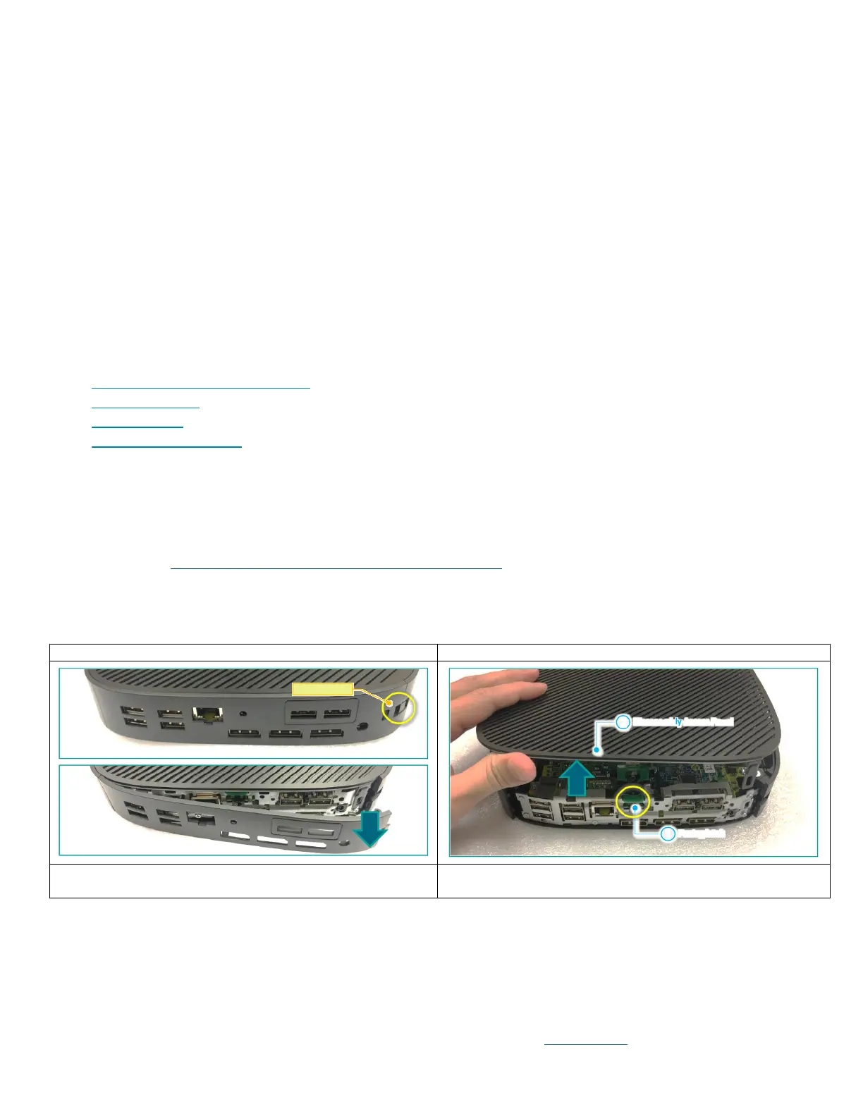
1. Remove Rear Cover
2. Remove access panel
3. Remove “+”M2 screws of option kit and option board
4. Remove “+”M2 screws of Rear-brkt
5. Remove T8-SSD screw and module
6. Remove shielding can
7. Remove DIMM
8. Remove speaker conn
9. Unfasten T15-M3 screws and disassembly MB
10. Remove speaker
11. Unfasten “+” M2 screws and internal antenna
12. Unfasten “+” M3 screws and internal antenna
13. Unfasten “+” M2 screws
14. Remove VESA cover by hand
15. Remove Bend cover by hand
NOTE - For disassembly instructions of the external power supply (EPS), external keyboard (KB) external mouse and external
cables and cords, refer to the links below:
• Generic External Power Supply (EPS)
• Generic Keyboard
• Generic Mouse
• Generic cables and cords
3.2 Location of components requiring selective treatment. The photos and/or graphics below identify the location of the parts
or components requiring selective treatment within the main unit. For End-of-Life product disassembly instructions of external
accessories including external power supply (EPS), external keyboard (KB) external mouse and external cables and cords, refer
to the following URL: End-of-Life Product Disassembly Instructions (hp.com)
 Loading...