h. Top cover (see Top cover on page 85)
i. Speaker (see
Speaker on page 91)
When replacing the system board, be sure that the following components are removed from the
defective system board and installed on the replacement system board:
●
SIM (see
SIM on page 49)
●
Memory modules (see
Expansion memory module on page 52 and Primary memory module
on page 74)
●
WLAN module (see
WLAN module on page 57)
●
WWAN module (see
WWAN module on page 61)
●
RTC battery (see
RTC battery on page 73)
●
Bluetooth module cable (see
Bluetooth module cable on page 92)
●
Modem module (see
Modem module on page 97)
●
Fan/heat sink assembly (see
Fan/heat sink assembly on page 98)
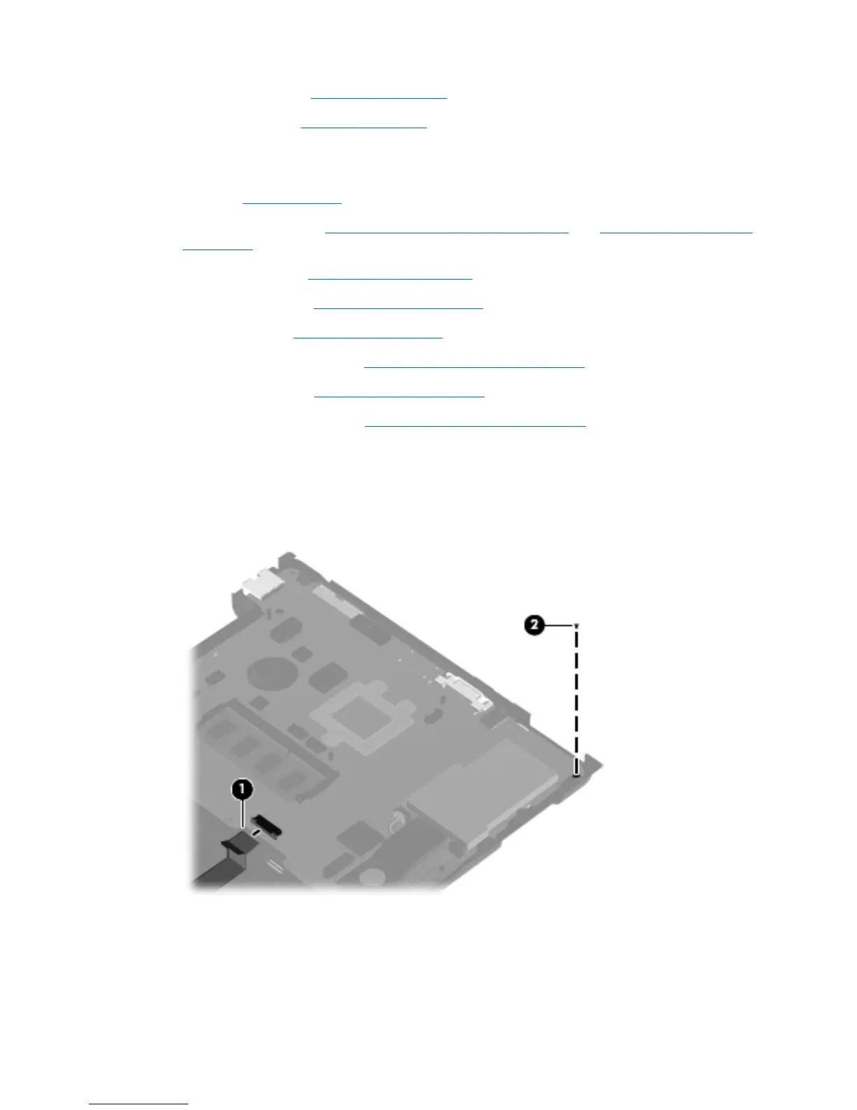
Remove the system board:
1. Release the ZIF connector to which the LED board cable is attached, and then disconnect the
LED board cable (1) from the system board.
2. Remove the Torx8 T8M2.5×5.0 screw (2) that secures the system board to the base enclosure.
3. Flex the left side of the base enclosure (1) until the RJ-11 jack and USB ports are clear of the
openings in the base enclosure.
4. Use the optical drive connector (2) to lift the left side of the system board (3) until it rests at an
angle.
ENWW Component replacement procedures 95
 Loading...