34
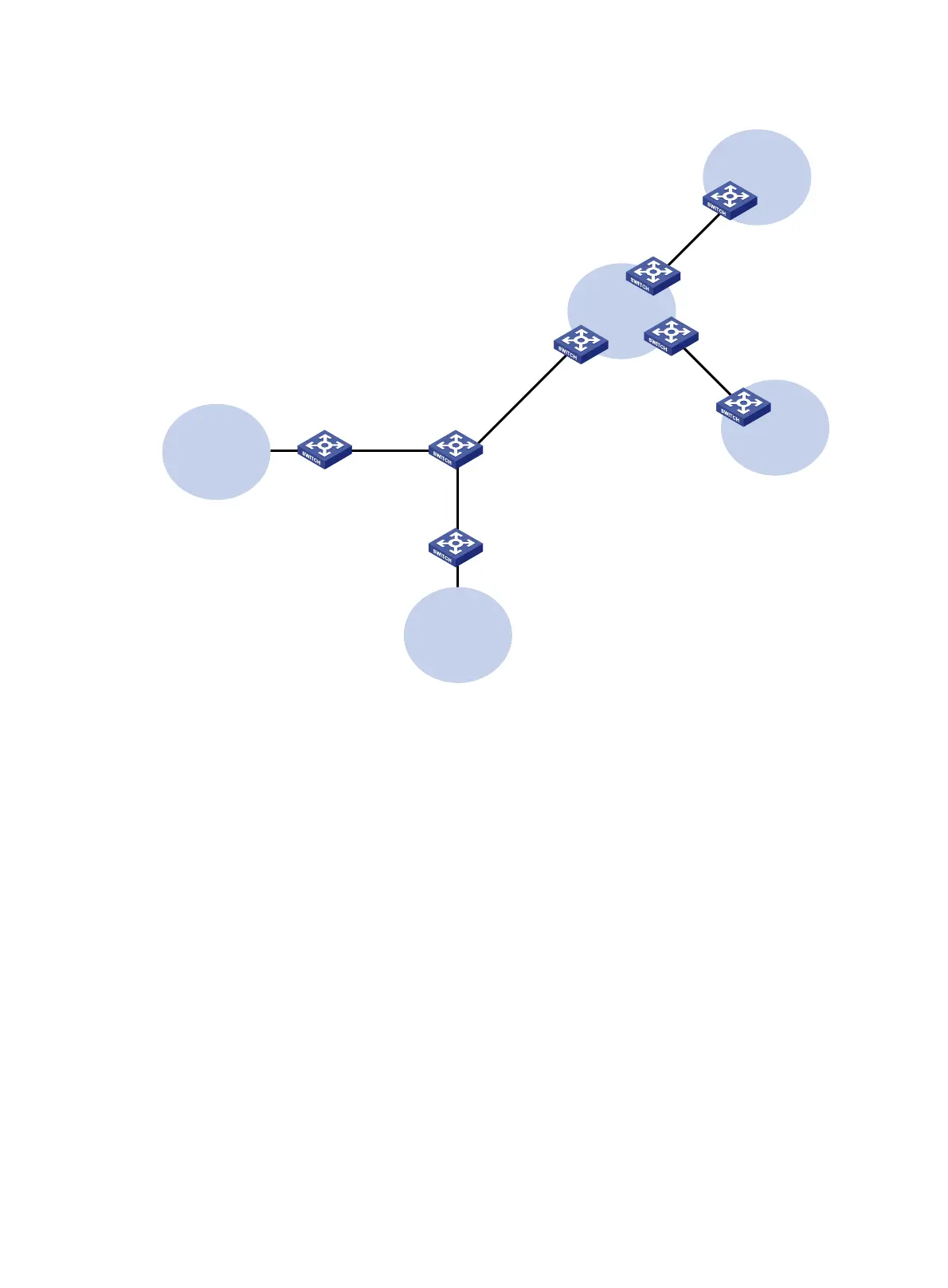
Figure 7 Network diagram
Configuration procedure
Assume that the system name of the MCE device is MCE, the system names of the edge devices of
VPN 1 and VPN 2 are VR1 and VR2, and the system name of PE 1 is PE1.
1. Configure the VPN instances on the MCE and PE 1:
# On the MCE, configure VPN instances vpn1 and vpn2, and specify an RD and route targets
for each VPN instance.
<MCE> system-view
[MCE] ip vpn-instance vpn1
[MCE-vpn-instance-vpn1] route-distinguisher 10:1
[MCE-vpn-instance-vpn1] vpn-target 10:1
[MCE-vpn-instance-vpn1] quit
[MCE] ip vpn-instance vpn2
[MCE-vpn-instance-vpn2] route-distinguisher 20:1
[MCE-vpn-instance-vpn2] vpn-target 20:1
[MCE-vpn-instance-vpn2] quit
# Bind VLAN-interface 10 to VPN instance vpn1, and configure an IPv6 address for the VLAN
interface.
[MCE] interface vlan-interface 10
[MCE-Vlan-interface10] ip binding vpn-instance vpn1
CE
VPN 1
Site 2
CE
VPN 2
Site 1
PE 1
PE 3
PE 2
VPN 2
2012::/64
VR 2
VPN 1
2012:1::/64
VR 1
MCE
Vlan-int10
2001:1::1/64
Vlan-int30: 30::2/64
Vlan-int40: 40::2/64
Vlan-int30: 30::1/64
Vlan-int40: 40::1/64
Vlan-int20
2002:1::1/64
Vlan-int10
2001:1::2/64
Vlan-int20
2002:1::2/64
Vlan-int11
2012:1::2/64
Vlan-int21
2012::2/64
 Loading...