Removal and replacement procedures 4–55
Remove the fan/heat sink assembly:
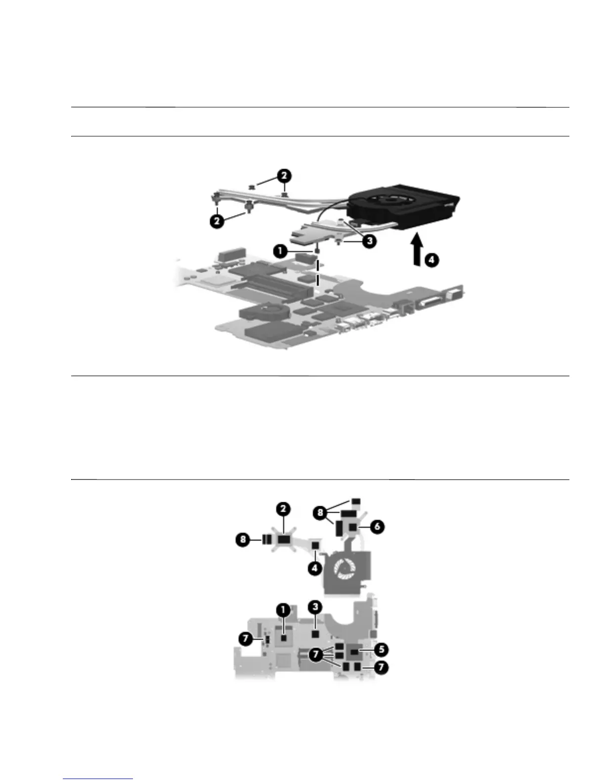
1. Disconnect the fan cable 1 from the system board.
2. Loosen the four Phillips PM2.0×10.0 captive screws 2 and the two Phillips PM2.5×5.0 captive screws 3 that
secure the fan/heat sink assembly to the system board.
✎
Due to the adhesive quality of the thermal material located between the fan/heat sink assembly and system board
components, it may be necessary to move the fan/heat sink assembly from side to side to detach the assembly.
3. Remove the fan/heat sink assembly 4.
✎
The thermal material must be thoroughly cleaned from the surfaces of the fan/heat sink assembly and the system
board each time the fan/heat sink assembly is removed:
■ Thermal paste is used on the processor 1 and the heat sink section 2 that services it.
■ Thermal pads are used on the Northbridge chip 3 and the heat sink section 4 that services it.
■ Thermal pads are used on various other system board components 5 and 7, and sections of the heat sink 6
and 8.
Replacement thermal material is included with all fan/heat sink assembly, system board, and processor spare part kits.
Reverse this procedure to install the fan/heat sink assembly.
 Loading...