To remove the toner level detection PCB
1. Remove the rear cover. See Rear cover.
2. Remove the top cover. See
Top cover.
3. Remove the rear top cover. See
Rear top cover.
4. Remove the right cover. See
Right cover.
5. Remove the high-voltage power supply PCB. See
To remove the high-voltage power
supply PCB.
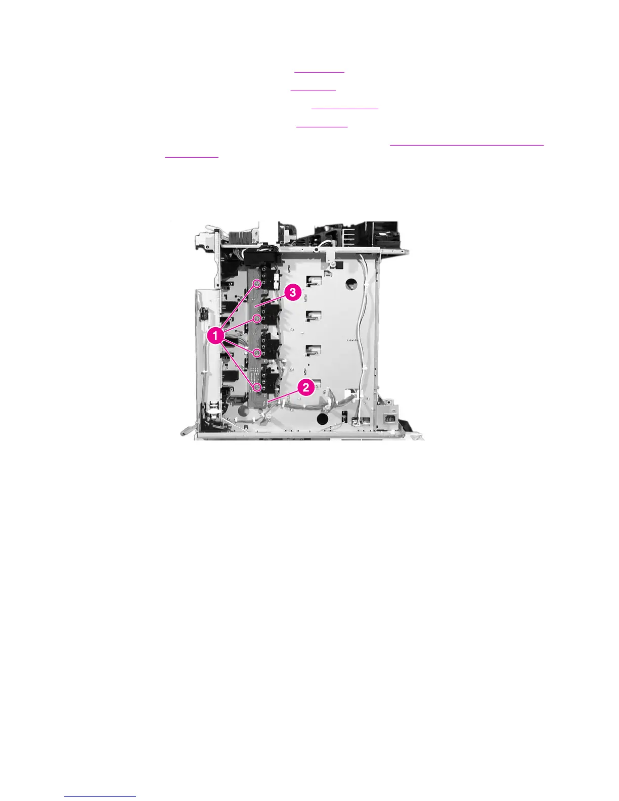
6. Remove the four screws shown in callout 1.
7. Disconnect the connector shown in callout 2.
8. Remove the toner level detection PCB (callout 3).
Figure 6-68.
Removing and replacing the toner level detection PCB
High-voltage contact blocks
Use the following steps to remove and replace the high-voltage contact blocks.
ENWW Internal components (right side) 235
 Loading...