CAUTION: A gear (callout 3) on the back of the assembly is not captive. Do not lose the
gear when handling the assembly.
Figure 1-278 Install the main drive assembly (1 of 8)
3
2
1
2. With the front door and right door closed, position the drive assembly near the product, and then
rotate it up and onto the chassis.
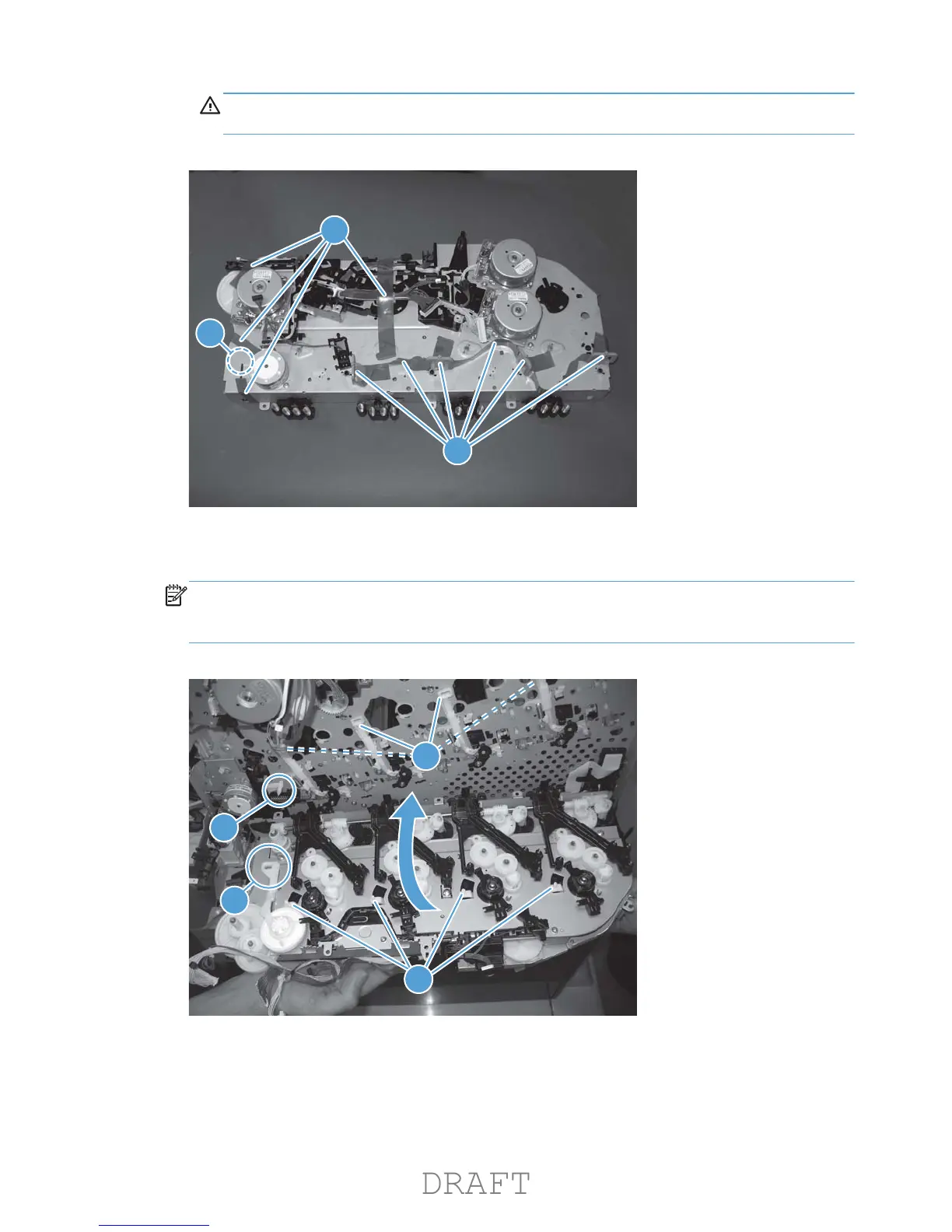
NOTE: Make sure that the right-door link arm shaft (callout 1) aligns with and is positioned in
the hole (callout 2) on the arm on the drive assembly, and that the pins on the assembly (callout 3)
are positioned in the holes in the link arms on the chassis (callout 4).
Figure 1-279 Install the main drive assembly (2 of 8)
2
1
3
4
202 Chapter 1 Removal and replacement ENWW
 Loading...