Figure 9-10 Replacing the ADF mylar shield (4 of 5) ..................................................................................... 600
Figure 9-11 Replacing the ADF mylar shield (5 of 5) ..................................................................................... 601
Figure 9-12 Removing the mylar-holder assembly (1 of 2) ............................................................................ 602
Figure 9-13 Removing the mylar-holder assembly (2 of 2) ............................................................................ 602
Figure 9-14 Removing the control panel (1 of 2) ............................................................................................ 603
Figure 9-15 Removing the control panel (2 of 2) ............................................................................................ 603
Figure 9-16 Removing the control panel overlays .......................................................................................... 604
Figure 9-17 Removing the formatter cage ...................................................................................................... 605
Figure 9-18 Removing the hard drive (1 of 2) ................................................................................................ 606
Figure 9-19 Removing the hard drive (2 of 2) ................................................................................................ 607
Figure 9-20 Removing the hard-disk drive cable ........................................................................................... 608
Figure 9-21 Removing the memory DIMM ..................................................................................................... 609
Figure 9-22 Removing the compact flash card .............................................................................................. 610
Figure 9-23 Removing the hinge flaps ........................................................................................................... 611
Figure 9-24 Removing the paper input tray .................................................................................................... 612
Figure 9-25 Related documentation and software ......................................................................................... 625
Figure 9-26 Internal components ................................................................................................................... 627
Figure 9-27 Cables and interfaces ................................................................................................................. 630
Figure 9-28 Control-panel overlays ................................................................................................................ 632
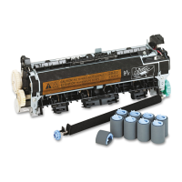
Figure 9-29 Maintenance kits ......................................................................................................................... 634
Figure 9-30 Memory ....................................................................................................................................... 636
Figure 9-31 ADF Assembly ............................................................................................................................ 638
Figure 9-32 ADF base assembly .................................................................................................................... 640
Figure 9-33 Separation pad case ................................................................................................................... 642
Figure 9-34 Pickup roller assembly ................................................................................................................ 644
Figure 9-35 Control panel cover assembly ..................................................................................................... 646
Figure 9-36 Control panel assembly .............................................................................................................. 648
Figure 9-37 ADF left cover ............................................................................................................................. 650
Figure 9-38 ADF input tray assembly ............................................................................................................. 652
Figure 9-39 Mylar holder assembly ................................................................................................................ 654
Figure 9-40 Scanner components .................................................................................................................. 656
Figure 9-41 Bottom unit assembly .................................................................................................................. 658
Figure 9-42 Power plug .................................................................................................................................. 660
Figure 9-43 Top formatter .............................................................................................................................. 662
Figure 9-44 Fan assembly .............................................................................................................................. 664
Figure 9-45 Keyboard assembly .................................................................................................................... 666
Figure 9-46 Lower cover assembly ................................................................................................................ 668
Figure 9-47 Scanner rear cover ..................................................................................................................... 670
ENWW xxi
 Loading...