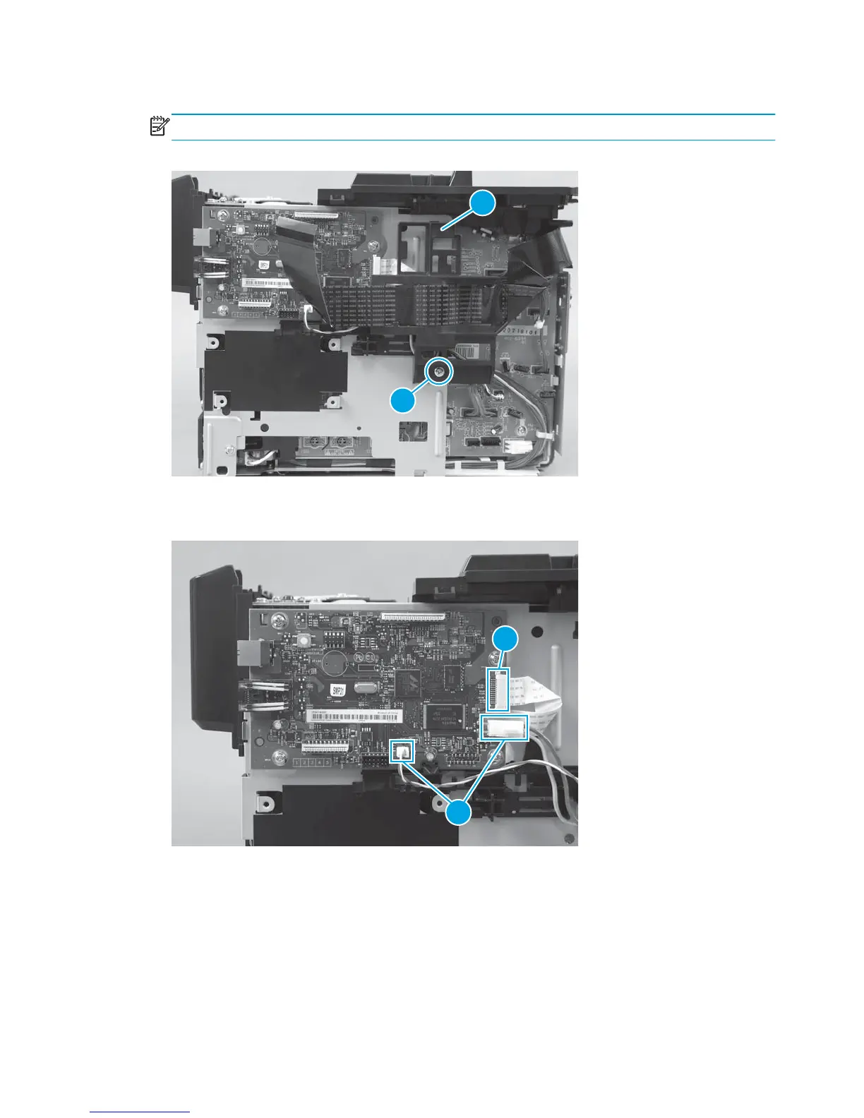
2. Remove one screw (callout 1), and remove the FFC guide (callout 2).
NOTE: The FFC guide might look slightly different, but the procedure is the same.
Figure 1-50 Remove the formatter PCA for the M176 model (2 of 4)
2
1
3. Disconnect two connectors (callout 1) and one FFC (callout 2).
Figure 1-51 Remove the formatter PCA for the M176 model (3 of 4)
1
2
40 Chapter 1 Removal and replacement ENWW
 Loading...