Do you have a question about the HP NetServer LC II and is the answer not in the manual?
This document serves as an installation road map for the HP NetServer LC II, guiding users through the setup, configuration, and maintenance of the server. It is designed for individuals involved in the installation, administration, and troubleshooting of LAN servers, assuming a basic understanding of computer equipment servicing and awareness of hazards associated with energy levels.
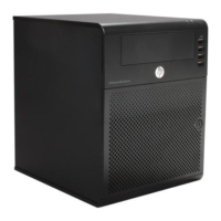
The installation process begins with a comprehensive overview of the HP NetServer LC II's features, including its front bezel components like the power switch, power LED, keyboard lock switch, and keyboard lock LED. The front bezel also houses key lock positions (locked/unlocked), flexible disk drive (Shelf 1), serial number, CD-ROM drive (Shelf 2), and additional shelves (3-6) for mass storage. For models with hot-swap capabilities, a hot-swap subsystem with a locking bar is present. The rear view reveals essential ports such as Serial B, Serial A, Parallel, Mouse, Keyboard, and Monitor ports, along with a management port for remote console management via the Integrated Remote Assistant, a network connector, and a power connector. Internally, the server features a CPU extractor handle, system board, retaining latches, voltage regulator module, backplane, power supply module, terminator board, system switches, and a connector for an external battery. Specific slots are designated for components like the Network Interface Controller Board (Slot 6) and an optional Disk Array Controller Board (Slot 5), alongside a SCSI connector and Flexible Disk Drive (FDD) connector.
The initial step involves verifying the contents of the shipping box against the provided checklist. Any discrepancies or damages should be reported to the reseller. If not rack-mounted, the server should be secured on its anti-tip pedestal, ensuring proper alignment and engagement until it locks into place. For rack installations, specific instructions in Section 13 and the HP NetServer Rack Installation Road Map should be consulted.
Next, users are instructed to obtain the HP Navigator CD-ROM Release History to ensure they have the latest software versions. This history, accessible via fax, Internet WWW, Internet FTP, BBS, or CompuServe, provides updates and instructions for obtaining current releases. It also guides users on accessing drivers and utilities for non-HP components from their respective manufacturers.
Connecting the monitor, keyboard, and mouse is a straightforward process, followed by plugging in the power cords for both the server and monitor. If an Uninterruptible Power Supply (UPS) is used, its instructions should be followed for installation and power-on.
Preparation for installation involves booting the HP Navigator CD-ROM. Users power on the monitor and server, insert the CD-ROM, and restart the server if necessary. The Navigator allows for language selection, time/date settings, and BIOS language changes. Viewing the Readme file, accessible from the Navigator Main Menu, provides crucial installation information. Optionally, the Diagnostic Assistant can be run from the Navigator CD-ROM to verify hardware integrity. The Information Assistant, which aids in server installation, is recommended to be installed on a client system for easier use. Users can also visit the Order Assistant online to find tested HP and third-party components, accessories, cables, and connectors. For those planning to install optional IntranetWare software, obtaining the key before NOS installation is advised.
Removing the covers is necessary for installing options other than hot-swap modules, accessory boards, or non-hot-swap mass storage devices. This requires a flat 1/4-inch screwdriver and a T15 TORX® driver. A critical warning emphasizes disconnecting the power cord and telephone cables before removing covers to prevent exposure to high energy levels and shock hazards. The power switch does not turn off standby power, so disconnecting the power cord is essential. The process involves turning off the server, unlocking the front bezel with the provided key, pulling the pocket on the bezel to swing it outward, and then removing it. The top cover is removed by loosening thumbscrews, pulling it forward slightly, lifting it to create a 1-inch gap, pushing it back, and then lifting it off. A caution advises against lifting the top cover too high to prevent damage. If needed, a side cover can be removed by grasping its two tabs, pulling upward and outward, and lifting it off. An ESD warning highlights the sensitivity of electronic devices and the necessity of using a grounded wrist strap and work surface.
Installing additional memory (DIMMs) requires adherence to specific rules: only HP DIMMs listed in the Technical Reference Label, Information Assistant, or Order Assistant should be used, in 32 MB, 64 MB, or 128 MB combinations, and they can be installed in any of the four DIMM sockets in any order. The system board must first be removed by lifting retaining latches, grasping the metal bracket, and placing it component-side up on a static-dissipating work surface, ensuring the metal crosspiece is OFF the work surface. DIMMs are then installed by spreading retaining clips, aligning notches with socket keys, and inserting them fully until the clips close. The system board is reinserted by aligning plastic rails with chassis guides and pushing it down. If accessory boards are to be installed in slots 5 or 6, the system board is left in a raised position; otherwise, it is pushed down firmly and secured by lowering the retaining latches. A caution reiterates the importance of installing DIMMs on a flat, static-dissipating surface with the metal crosspiece off the work surface to prevent damage.
Installing all accessory boards involves removing covers and raising the system board if not already done. Users should consult the documentation included with each accessory board for special instructions and preferred slot locations, considering boot order. For ISA non-Plug-and-Play boards, reserving system resources (memory addresses, I/O addresses, IRQs, and DMA channels) is mandatory using the Setup utility. Slot covers are removed for each slot to be used, and for full-length PCI boards, the board retainer is also removed. Boards are then inserted into desired slots, fastened with mounting screws, and required cables are connected. Finally, the system board is lowered and secured. Boot device priority for PCI controllers is determined by slot location, with the system searching in a specific order: IDE CD-ROM, flexible disk drive, embedded SCSI controller, and then PCI boards in slots 6, 5, 4, 3, 2, 1. The backplane offers six accessory board slots: slots 2 through 6 for 32-bit PCI boards (slot 6 preinstalled with NIC, slot 5 for optional DAC), and slot 1 for 16-bit ISA or 32-bit PCI boards. Accessory boards are identified by the offset of the bracket and the shape of the edge connector.
Installing additional mass storage devices includes preinstalled components like a flexible disk drive in Shelf 1, an IDE CD-ROM drive in Shelf 2, and in some models, a SCSI hard disk drive in Shelf 3 or a hot-swap subsystem supporting up to three hot-swap drive modules. For non-hot-swap SCSI drives, users must set the SCSI address on the drive jumpers to an unused address, ensuring the SCSI termination enable jumper (TE) is OFF. The drive is then installed in an empty mass storage shelf, and SCSI and power cables are connected, using a wide-to-narrow SCSI cable adapter for narrow (50-pin) SCSI tape drives. Hot-swap disk drive modules can only be installed in hot-swap subsystems. Default SCSI addresses for hot-swap subsystems are 1, 0, and 3 from left to right. If conflicts arise with non-hot-swap SCSI devices, the hot-swap SCSI addresses can be changed by moving switches on the rear of the subsystem. Removing the locking bar involves inserting a key, pressing the lock, turning clockwise, sliding the bar left, and lifting it. To remove a module, shipping plugs are removed, the locking tab is depressed, the locking lever lifted, and the module removed. To install a module, shipping plugs are removed, the locking lever is lifted, the module inserted, and the lever depressed. Replacing the locking bar involves aligning tabs with trim bezel slots, inserting the bar, sliding it right, inserting the key, and turning counterclockwise to lock it. A caution advises careful depression of the locking lever to avoid breakage. SCSI addressing examples illustrate jumper settings for wide (68-pin) SCSI devices and switches for hot-swap subsystems, emphasizing unique SCSI IDs and proper termination.
Replacing all covers and connecting all cables is the next step. If the system board was raised, it is lowered and secured by pushing it down and lowering the retaining latches. Side covers are replaced by inserting the lower channel onto the chassis lip and pressing the top until it snaps into place. The top cover is replaced by aligning its rear edge with the chassis, lowering the front, pulling it forward slightly to catch on the chassis, and tightening thumbscrews. The front bezel is aligned and pressed firmly into place, then locked with the key. Finally, the power cord and all other cables are connected. A caution warns against operating the server without all covers to prevent overheating and damage.
Verifying installed accessories is optional. Users can turn on the server and monitor to view the boot screen, which lists detected hardware like CPU, DIMMs, and PCI/ISA boards. Note that SCSI devices connected to a disk array controller board (DAC) or ISA non-Plug-and-Play boards are not displayed at boot time.
Configuring the HP NetServer involves turning on the server and monitor, inserting the HP Navigator CD-ROM, and restarting. If an ISA non-Plug-and-Play board was installed, system resources must be reserved using the Setup utility (accessed by pressing F2 during boot). Within Setup, users navigate to "Configuration" and "ISA non-Plug-and-Play Devices" to adjust values. The Configuration Assistant and Installation Assistant are run from the HP Navigator Main Menu, with "Express" mode being the default for configuration. "Custom" and "Replication" modes are also available. For Console Redirection with Integrated Remote Assistant, a utility partition must be created, automatically in "Express" mode or manually in "Custom" mode. Users then select the Network Operating System (NOS) and its version. For certain versions of Novell NetWare / IntranetWare or Microsoft Windows NT Server, HP's automated NOS installation mode can be chosen. Manual NOS installation is used for other NOSs or if HP components were replaced. Remote Management is configured using the "Configure Remote Management" option, which launches the utility for Integrated Remote Assistant. If a disk array is present, it is configured using the "Configure Disk Array" option, which launches the utility for the HP NetRAID Series. Finally, the NOS is installed, either guided by HP display screens for automated installation or manually by creating driver diskettes, saving and printing NOS Installation Instructions, and following vendor-supplied utilities. HP NetServer management is then set up by referring to the HP NetServer Management Reference Guide and installing HP TopTools.
The final step, if applicable, is installing the server in a rack assembly. This requires consulting the HP NetServer Rack Installation Road Map, the HP NetServer Rack Assembly and Cabling Reference Guide, and the rack installation kit instructions. After rack installation, users are directed back to the HP NetServer Rack Installation Road Map.
| Processor | Intel Pentium Pro |
|---|---|
| Processor Speed | 200 MHz |
| Form Factor | Tower |
| Chipset | Intel 440FX |
| RAID Support | Optional RAID controller |
| RAM | Minimum 32 MB, Maximum 512 MB |
| Network Interface | Integrated 10/100Base-T Ethernet |
| Operating System | Windows NT, Novell NetWare |