Engine control unit (ECU)
The ECU coordinates all device functions, according to commands that the formatter sends. It drives
the laser/scanner system, the image formation system, and the pickup/feed/delivery system.
The ECU contains the following components:
●
Engine controller PCA
●
Low-voltage PCA
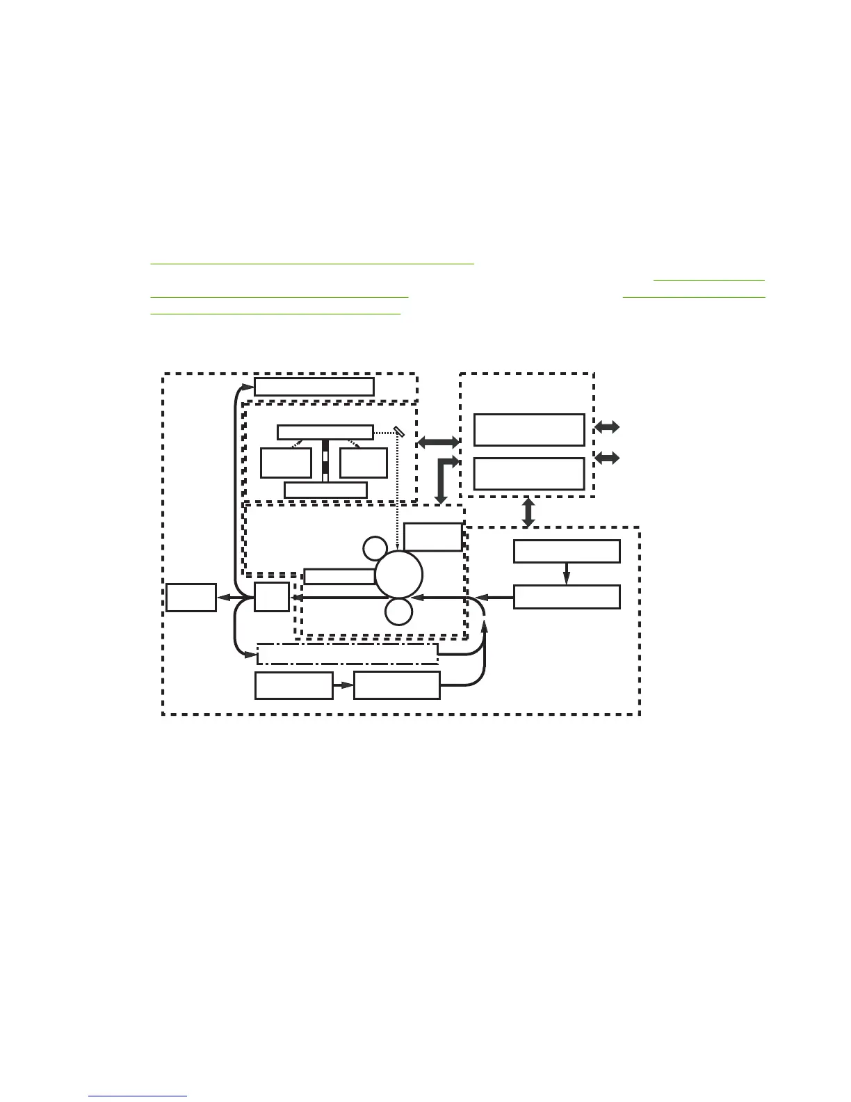
Figure 4-2 Print engine general structure on page 47 shows the relationship of the ECU to the pickup/
feed/delivery system, the laser/scanner system, and the image-formation system.
Figure 4-3 Engine
control system circuit diagram on page 48 provides the ECU circuit diagram. Figure 4-4 Low-voltage
power supply circuit diagram on page 49 shows the low-voltage power supply circuit on the ECU.
METSYS RENNACS/RESAL
ror
r
im
gninna
cS
resaL
e
doid
Rear
output bin
D
B
tiucric
r
ettamroF
DEEF/PUKCIP
METSYS
ti
n
u
g
n
i
nae
l
C
Fuser
gnip
o
leveD
t
i
nu
EGAMI
NOITAMROF
METSYS
t
i
nu
deef xe
l
puD
r
ef
sn
arT
gnigrahc
r
e
ll
or
r
o
to
m
r
ennac
S
-otoh
P
evitisnes
murd
ECU
rellortnoc e
n
ignE
ACP
Tray 2
tin
u
pu
k
cip
Tray 1
Tray 1 pickup unit
Tray 2
y
r
a
mi
r
P
g
nig
r
ahc
re
l
lo
r
egatlov-hgiH
ACP
y
l
p
p
u
s
rew
o
P
noi
t
pO
Output bin
Figure 4-2 Print engine general structure
ENWW Basic operation 47
 Loading...