a.
Hard drive (see
Hard drive on page 51)
b.
Optical drive (see
Optical drive on page 59)
c.
Switch cover (see
Switch cover on page 61)
d.
Keyboard (see
Keyboard on page 65)
e.
Speaker assembly (see
Speaker assembly on page 63)
f.
Display assembly (see
Display assembly on page 68)
g.
Top cover (see
Top cover on page 74)
h.
Audio board (see
Audio board on page 85)
i.
USB/power connector board (see
USB/power connector board on page 81)
When replacing the system board, be sure that the following components are removed from the defective
system board and installed on the replacement system board:
●
Memory modules (see
Memory module on page 53)
●
RTC battery (see
RTC battery on page 55)
●
WLAN module (see
WLAN module on page 56)
●
Bluetooth module (see
Bluetooth module on page 78)
●
ExpressCard assembly (see
ExpressCard assembly on page 79)
●
Fan/heat sink assembly (see
Fan/heat sink assembly on page 86)
●
Processor (see
Processor on page 88)
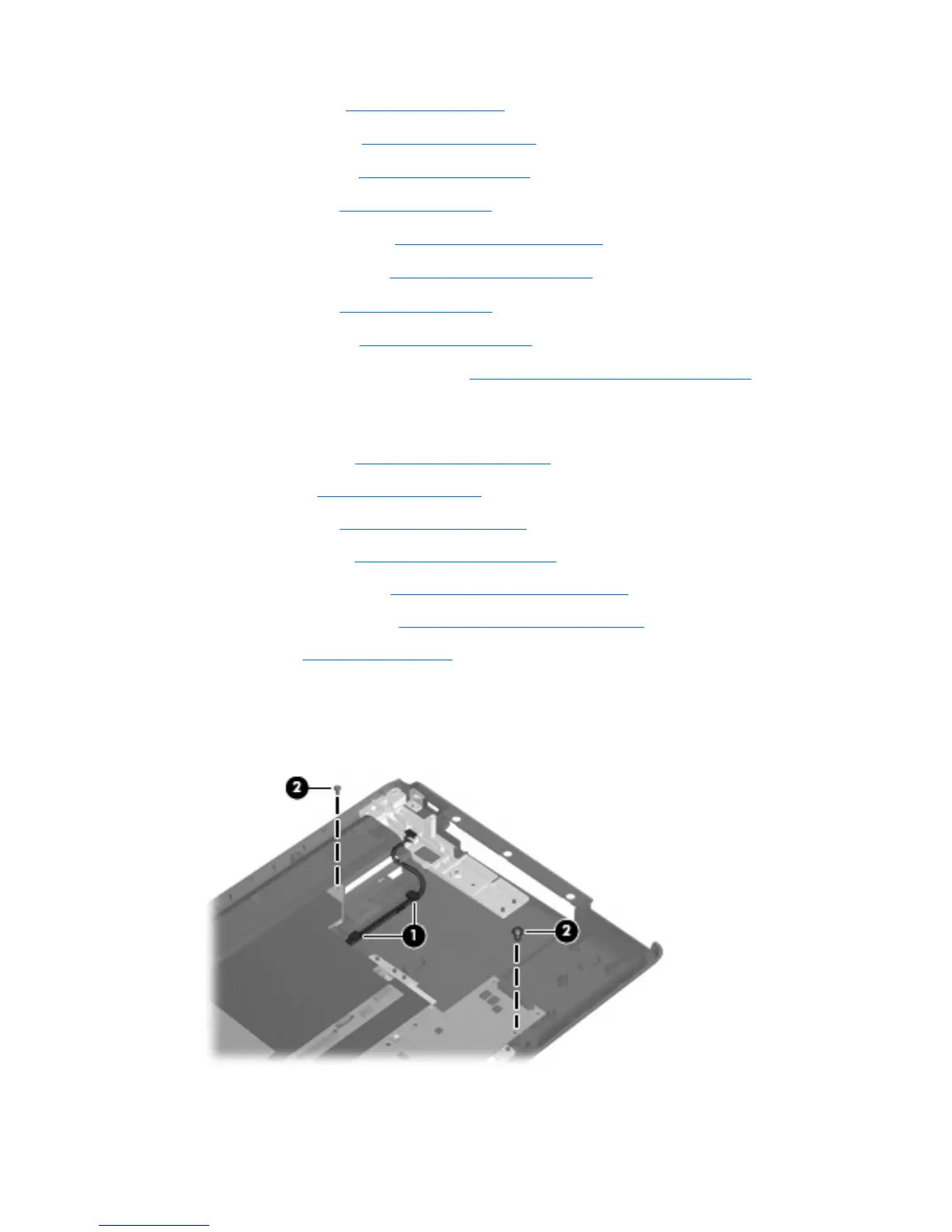
Remove the system board:
1. Remove the USB/power connector board cable (1) from the clips built into in the base enclosure.
2. Remove the two Phillips PM2.5×4.0 screws (2) that secure the system board to the base enclosure.
Component replacement procedures 83
 Loading...