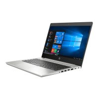
2. Remove the 14 T8 slotted-Torx 2.5×5.0 screws (1) and the 3 PM2.0×3.0 screws (2) that secure
the top cover to the base enclosure.
3. If installed, remove the ExpressCard slot bezel (1), release the top cover from the sides of the
base enclosure (2), and then remove the top cover (3).
Reverse this procedure to install the top cover.
Component replacement procedures 99
 Loading...