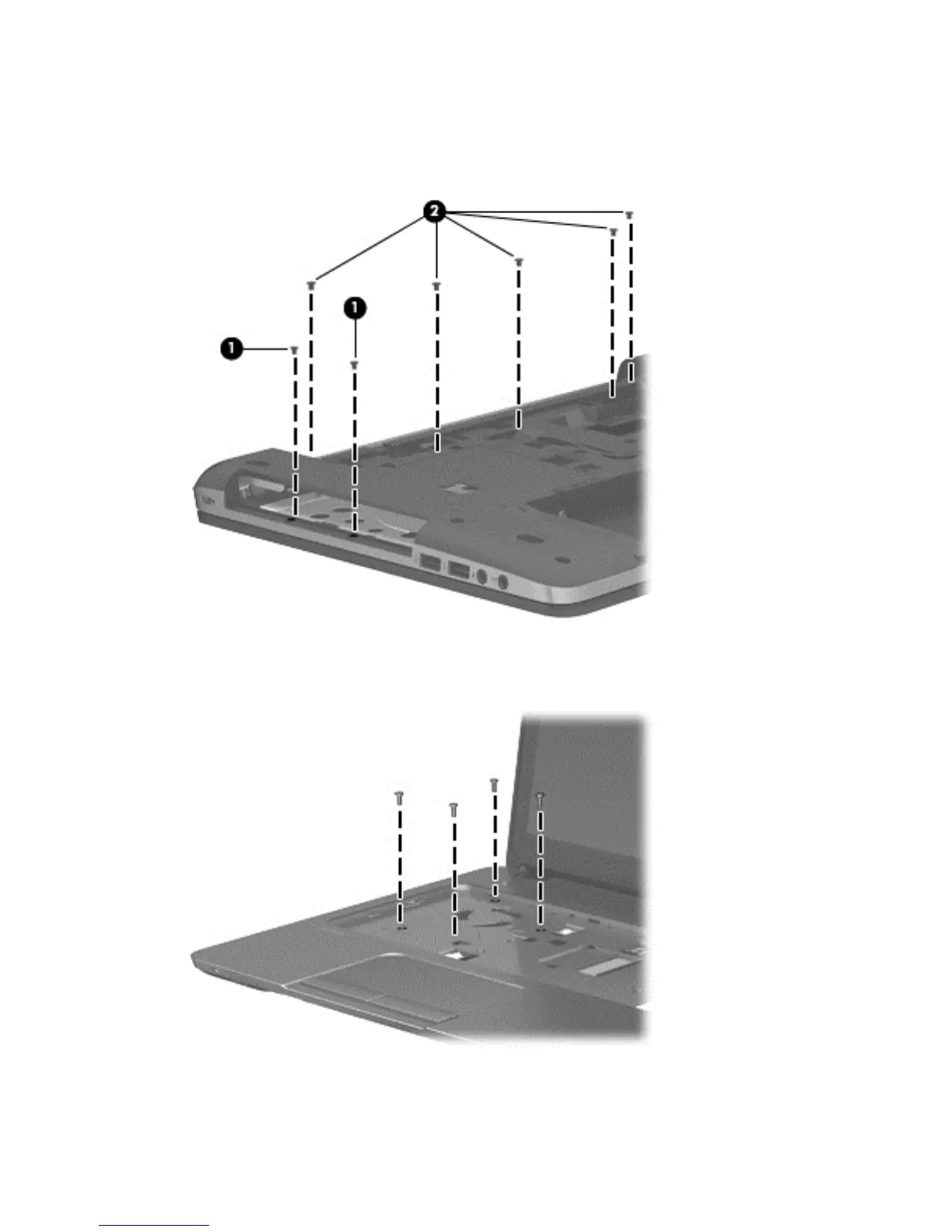
4. Remove the following screws:
(1) 2 Phillips PM2.0×3.0 screws from the optical drive bay
(2) 5 Phillips PM2.5×3.0 screws from the battery bay
5. Position the computer upright and open it as far as possible.
6. Remove the 4 Torx T8M2.5×6.0 screws from the top of the computer.
56 Chapter 6 Removal and replacement procedures for Authorized Service Provider parts
 Loading...