4. Install the Switch Hardware (Continued)
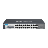
M-4 tap
screws
Ventilation
Wall (or Under-Table):
For wall or under-table mounting,
use a #1 Phillips (cross-head) screwdriver and the 20-mm M4
tap screws (included). For screw positions, see the mounting
template on page 4. (Under-Table: After installation, a third
screw may be used to prevent switch movement.)
For wall-mounting, the network ports must be facing up (see
fi
gure). Do not mount the switch with ports facing down, or
ventilation ducts on the side of the switch facing up or down.
(See “Safety Precautions” on page 3.)
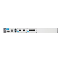
Rack Mounting: A speci
al rack-mounting kit is included. Use a #1 Phillips (cross-head) screwdriver to attach the special
brackets to the switch using the eight 8-mm M4 screws. Then use the four number 12-24 screws to secure the brackets to the
rack.
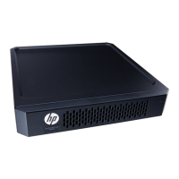
5. (Optional) Lock the Switch. Use a Kensington lock or
similar device (not included) to physically secure the switch.
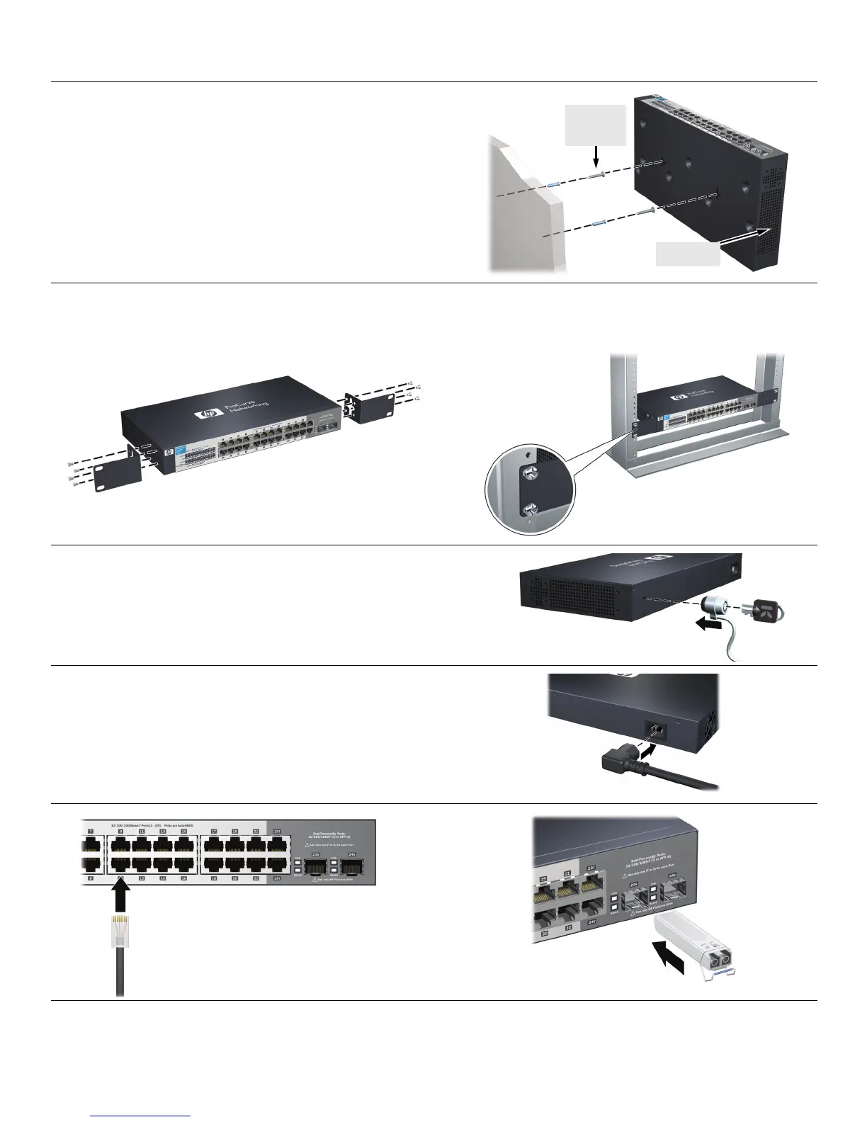
6. Power On the Switch and Connect Network Cables.
For transceiver connections, use o
nly supported HP ProCurve
mini-GBIC/SFP transceivers.
After installing a transceiver, allow it to initialize (wait a few
second
s) before removing it.
2
QSG-1410-24G-Feb2010.fm Page 2 Thursday, February 11, 2010 3:21 PM
 Loading...