2-13
Installing the Switch
Installation Procedures
Wall or Under-Table Mounting
You can mount the switch on a wall or under a table. A special kit for wall and
under-table mounting is included with the switch.
WARNING For safe operation, do not mount any of the switches with side
ventilation ducts facing up or down.
For the 1410-24G Switch, the network ports must be facing up. Do not
mount the switch with ports facing down.
For the 1410-16G Switch and 1410-8G Switch, the network ports may
face up or down.
Caution The switch should be mounted only to a wall or wood surface that is at least
1/2-inch (12.7 mm) plywood or its equivalent.
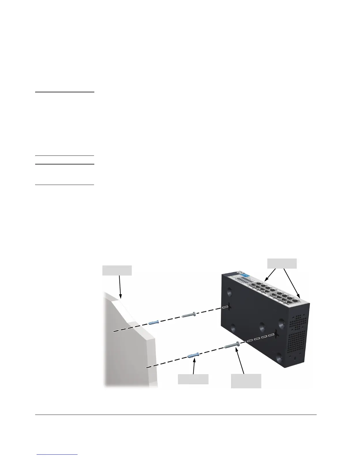
1. Position the mounting template (included in the Quick Setup Guide) in
the required location, and mark the position for the mounting screws.
2. Use a #1 Phillips (cross-head) screwdriver and two of the included 20-mm
M4 tap screws to mount the switch on the wall or wood surface.
Wall plugs are included in the accessory kit for use with plastered brick
or concrete walls.
Figure 2-8. Wall Mounting the Switch
 Loading...