Index – 3
precautions
mounting the switch … 2-3
power requirements … 2-3
preparing the installation site … 2-5
R
rack
mounting precautions … 2-3
mounting the switch in … 2-9
recycle statements … C-1
regulatory statements … B-8
Reset button
location on switch … 1-3
resetting the switch
troubleshooting procedure … 3-5
S
safety and regulatory statements … B-1
safety specifications … A-2
segment switch
sample topology … 2-23
self test
Fault LED behavior … 2-8
LED behavior during … 2-8
Power LED behavior … 2-8
SFP ports … 1-1
slots for mini-GBICs
location on switch … 1-3
specifications
acoustic … A-2
electrical … A-1
environmental … A-2
physical … A-1
safety … A-2
straight-through cable
pin-out … A-10, A-12
switch
connecting to a power source … 2-15
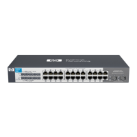
description … 1-1
electrical specifications … A-1
environmental specifications … A-2
features … 1-6
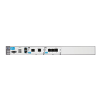
front panel description … 1-3
included parts … 2-1
LED descriptions … 1-4
mounting in a rack or cabinet … 2-9
mounting on a wall … 2-13
mounting on horizontal surface … 2-14
physical specifications … A-1
switch operation
verifying after installation … 2-6
T
testing
diagnostic tests … 3-5
end-to-end communications … 3-5
switch operation … 3-5
twisted-pair cabling … 3-5
tips for troubleshooting … 3-1
topologies
effects of improper topology … 3-2
samples of … 2-22
troubleshooting … 3-1
basic tips … 3-1
common network problems … 3-1
connecting to fixed full-duplex devices … 3-1
diagnostic tests … 3-5
effects of improper topology … 3-2
effects of non-standard cables … 3-2
testing end-to-end communications … 3-5
testing the switch … 3-5
testing the twisted-pair cables … 3-5
twisted-pair cable
cross-over cable pin-out … A-11
pin-outs … A-8, A-10, A-12
straight-through cable pin-out … A-10, A-12
switch-to-computer connection … A-10, A-12
switch-to-switch or hub connection … A-11
testing … 3-5
twisted-pair ports
HP Auto-MDIX feature … A-8
 Loading...