EasyManuals Logo

HP ProLiant ML110 - G2 Server Maintenance And Service Guide

HP ProLiant ML110 - G2 Server
98 pages
To Next Page IconTo Next Page
To Previous Page IconTo Previous Page
Page #19 background imageLoading...
Page #19 background image
Removal and Replacement Procedures
Drive Bay Configuration
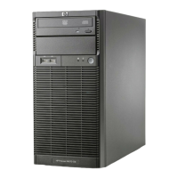
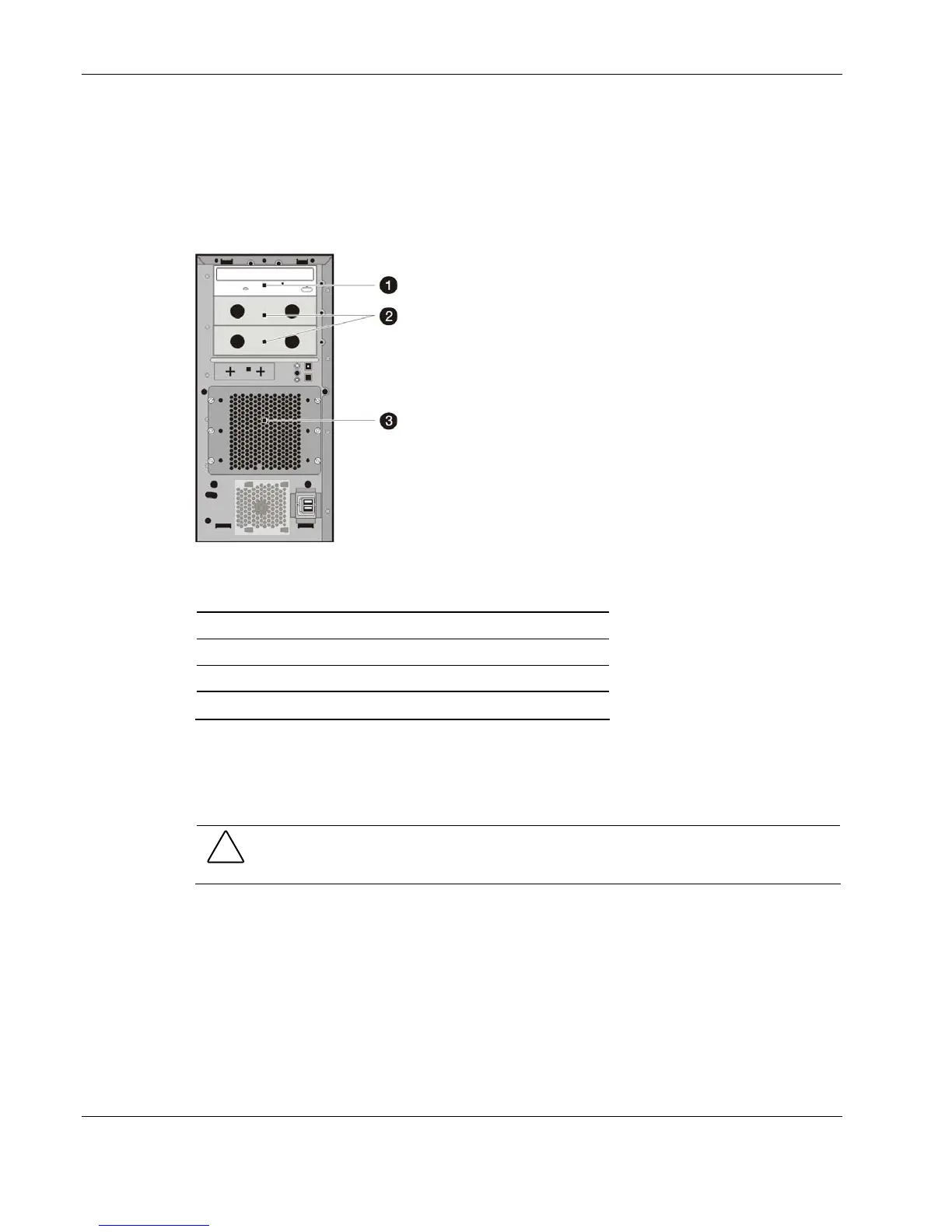
The server supports a maximum of seven internal drives. The upper drive bay is for
removable media devices, while the lower drive bay is for an HDD cage. The upper drive bay
contains a one-half height IDE CD-ROM drive and two empty full-height drive bays. The
lower drive bay can accommodate a hot-plug or a non-hot-plug HDD cage.
Figure 2-7: Drive bay configuration
Item Description
1 IDE CD-ROM drive
2 Full-height drive bays (empty)
3 HDD cage
Note: Figure 2-7 shows a non-hot-plug HDD cage.
Cable Routing Diagrams
Figure 2-8 through Figure 2-12 show the cable routing for the server.
CAUTION: When routing cables, be sure that the cables are not in a position where they can
be pinched or crimped.
2-10 HP ProLiant ML110 Generation 2 Server Maintenance and Service Guide

Other manuals for HP ProLiant ML110 - G2 Server

Questions and Answers:

Question and Answer IconNeed help?

Do you have a question about the HP ProLiant ML110 - G2 Server and is the answer not in the manual?

HP ProLiant ML110 - G2 Server Specifications

General IconGeneral
Server TypeTower
ChipsetIntel E7210
Memory TypeDDR SDRAM
Maximum Memory4 GB
Optical DriveOptional
Processor Sockets1
Memory Slots4
Form FactorTower
ProcessorIntel Pentium 4
Storage ControllerIntegrated SATA
Drive Bays2 x 3.5" internal
Network ControllerIntegrated Broadcom Gigabit Ethernet
Power Supply300W
Operating System SupportMicrosoft Windows Server 2003, Red Hat Linux

Related product manuals