Hardware options installation 86
b.
Install the access panel (on page 23).
c. Slide the server back into the rack.
18. Connect each power cord to the server.
19. Connect each power cord to the power source.
20. Press the Power On/Standby button.
The server exits standby mode and applies full power to the system. The system power LED changes
from amber to green.
21. Do one of the following:
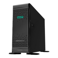
o For tower models, install the bezel.
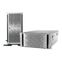
o For rack models, if removed, install the security bezel (on page 45).
Drive backplane expander option
Before installing the backplane expander option kit, you must update the firmware on the HP Smart Array
P420 or P420i Controller to version 2.14 or higher. Download the latest firmware for the Smart Array P420
and P420i controllers from the HP website (http://www.hp.com/go/spp).
NOTE: The drive backplane expander options allow up to 18 LFF / 24 SFF drives to be
managed under one single controller.
Installing the 6 bay LFF drive backplane expander
1. Do one of the following:
o For tower models, open and remove the bezel ("Remove the tower bezel" on page 20).
o For rack models, if installed, remove the security bezel (on page 20).
2. Power down the server (on page 19).
3. Remove all power:
a. Disconnect each power cord from the power source.
b. Disconnect each power cord from the server.
4. For tower models, do the following:
a. Place the server on a flat, level surface with the access panel facing up.
b. Remove the access panel (on page 22).
5. For rack models, do the following:
a. Extend the server from the rack (on page 23).
b. Remove the access panel (on page 22).
c. Release thumbscrews and remove the rack bezel.
 Loading...